A kind of train hub steering self-correcting assembly

A train wheel and self-calibration technology, which is applied in the field of rail transit, can solve problems that affect the normal steering of trains, affect the ride experience, and aggravate train bumps, etc., so as to improve the ride experience, improve the squeeze effect, and extend the maintenance cycle Effect

Active Publication Date: 2020-09-22
亚太空列(河南)轨道交通有限公司
View PDF4 Cites 0 Cited by
  • Summary
  • Abstract
  • Description
  • Claims
  • Application Information

AI Technical Summary

Problems solved by technology

[0004] When the inner rim of the train wheel hub transitions from the inner curved rail 3 to the straight point rail 5, there will be a short suspension time, and it will overlap the forged end of the straight point rail 5 from top to bottom. This phenomenon will bring bumps to the train and affect the experience of riding. At the same time, the end of the straight point rail 5 itself is formed by forging. The depth becomes deeper, which will further aggravate the bumps of the train
[0005] Simultaneously because there is a certain centrifugal force when the train turns, the outer rim of the wheel hub of the train will form an extrusion force on the side of the forged end of the straight point rail 5, and the extrusion marks on the side of the forged end of the straight point rail 5 will become larger. It will cause indentation, which will make the side of the forged end form a stepped surface, and the outer rim of the hub will easily climb to the top of the straight point rail 5 through the indentation. Serpentine movement will aggravate the bumps of the train, and in severe cases, it will cause the train to derail and seriously affect the normal steering of the train.

Method used


Image

  • A kind of train hub steering self-correcting assembly
  • A kind of train hub steering self-correcting assembly
  • A kind of train hub steering self-correcting assembly

Examples


Embodiment 1

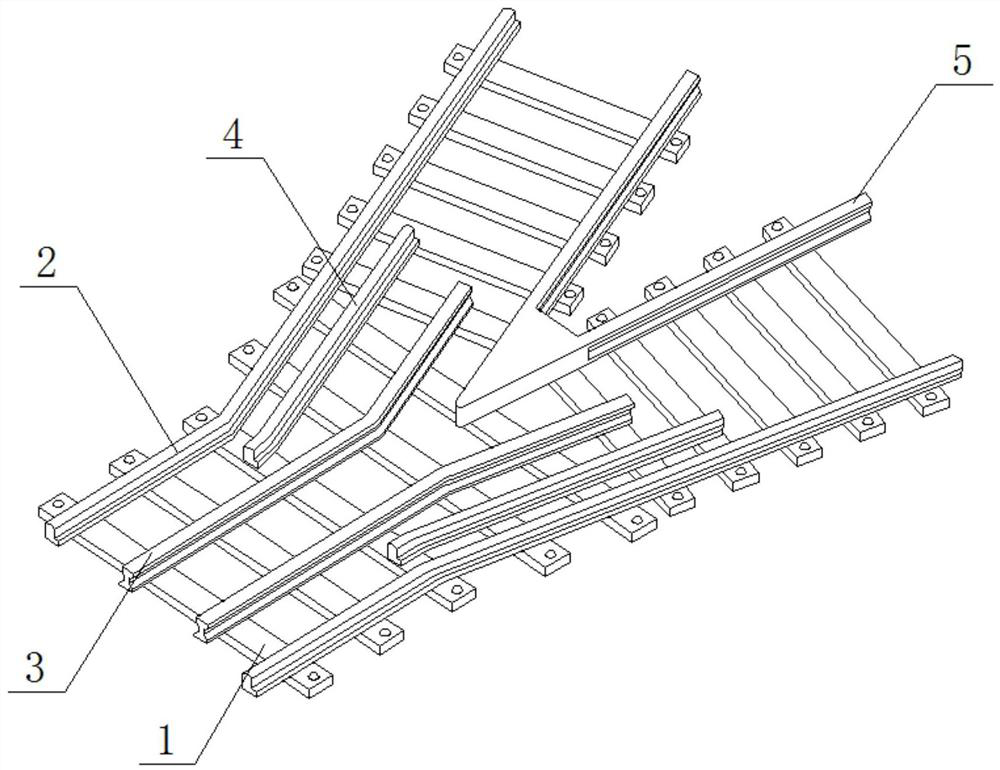
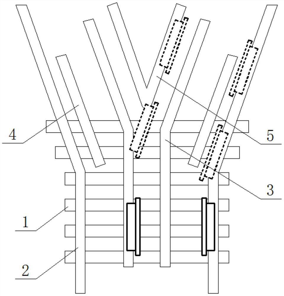
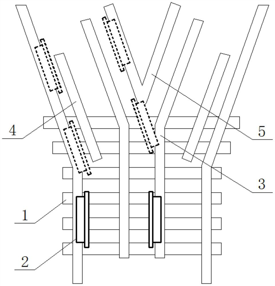
[0033] See Figure 4-8 , A train wheel steering self-correcting assembly, including sleepers 1 pre-installed on the ground and basic rails 2, inner curved rails 3, outer curved rails 4, and straight-point rails 5 conventionally arranged on the upper surface of the sleepers. The junction of the curved rail 3 and the straight tip rail 5 is fixedly provided with an energy dissipating gasket 6 on the surface of the sleeper 1, and the sleeper 1 is fixedly provided with a limit steel frame 7 at both ends of the energy dissipating gasket 6, and The limit steel frame 7 is close to the outer side wall of the straight rail 5;

[0034] The junction end of the inner curved guide rail 3 and the straight tip rail 5 is a solid arrangement, the inner curved guide rail 3 is provided with a rectangular placement groove 301 on one end surface close to the straight tip rail 5, and the bottom of the inner curved guide rail 3 is provided with three A limit slot 302 that penetrates the placement slot ...

Embodiment 2

[0043] See Picture 9 with Picture 10 The difference from the first embodiment is that the material of the coil 10 can also be a copper annular ring, and the length of the effective cutting magnetic field of the coil 10 is equal to the length of the permanent magnet 14, which can be selectively used according to the speed and quality of the train This setting reduces the overall impedance of the loop, and at the same time enhances the induced current generated by the loop. (The conductivity of copper is relatively stronger than that of iron, and the magnitude of the induced current increases with the number of cutting magnetic lines. This is current technology).

[0044] The working principle of the first embodiment and the second embodiment:


PUM


Abstract

The invention relates to the technical field of rail traffic, and discloses a train hub steering self-correcting assembly. The train hub steering self-correcting assembly comprises a sleeper which ispreinstalled on the ground surface, and a basic rail, an inner guide bent rail, an outer guide bent rail and a straight sharp rail which are conventionally arranged on the upper surface of the sleeper. An energy-dissipating gasket located on the surface of the sleeper is fixedly arranged at the joint of the inner guide bent rail and the straight sharp rail. By installing the energy-dissipating gasket at the joint of the straight sharp rail and the inner guide bent rail, an outer side rim of a train hub can be erected on the energy-dissipating gasket in advance during steering rail changing, the longitudinal pressure (energy-dissipating process) of the hub is counteracted through the elastic deformation of the energy-dissipating gasket, the longitudinal load of the hub is small when an inner side rim of the hub abuts against a forged section of the straight sharp rail, the abrasion to the forged section of the straight sharp rail is reduced, the service life of the forged section of thestraight sharp rail is prolonged on one hand, it can be ensured that the train hub can be prevented all the time from suspending and jolting on the other hand, the train taking experience of passengers is improved.

Description

Technical field [0001] The invention relates to the technical field of rail transit, in particular to a train wheel hub steering self-correcting assembly. Background technique [0002] Please refer to the structure of the train track at the turnout figure 1 , The principle of train lane change: the end of the inner curved rail 3 is connected with the switch, and the wheel hub of the train is changed lanes through the hidden tip rail on the switch to drive into the inner curved rail 3 , The process of redirecting the train hub to the basic rail through the guidance of the inner guide curved rail 3 and the outer guide curved rail 4. [0003] The structure of the straight tip rail 5 is to weld the ends of two straight steel rails together and forge them. The height of the ends is smaller than the height of the inner guide curved rail 3. The purpose is to allow the train hub to smoothly transition to the straight rail. On the switch rail 5, in order to ensure the normal steering on bo...

Claims


Application Information

Patent Timeline
Patent Type & Authority Patents(China)
IPC IPC(8): E01B7/00E01B7/02E01B7/10E01B7/20B61F9/00
Inventor 不公告发明人
Owner 亚太空列(河南)轨道交通有限公司
Why Eureka
Try Eureka