Concrete vibrating device and method

A vibrating device and concrete technology, applied in the direction of roads, road repair, roads, etc., can solve the problems of increasing manufacturing cost, affecting construction progress, increasing weight, etc., so as to reduce equipment manufacturing cost, improve construction efficiency, and reduce the number of installations. Effect

Pending Publication Date: 2019-05-31
湖北乾奥建设工程有限公司
View PDF8 Cites 5 Cited by
  • Summary
  • Abstract
  • Description
  • Claims
  • Application Information

AI Technical Summary

Problems solved by technology

The vibrating rod is commonly used for vibrating. Due to the large area inside, using a vibrating rod for vibrating requires a lot of labor, and the production efficiency is low, and the labor intensity of the workers is high. Moreover, due to manual vibration, the quality of the vibration cannot be achieved. Guaranteed
In order to solve this problem, the prior art mostly uses a vibrating machine, for example: the patent No. is "CN 204919284 U" and the name is "a vibrating device"; the patent number is "CN 201614541 U" and the name is "a kind of road Surface Concrete High-Frequency Vibration Machine", these two vibrating devices are not suitable for vibrating multi-layer concrete pavement, because the multiple plug-in vibrators on the vibrator are installed obliquely on the flip frame, so they can only be moved forward Concrete is vibrated. If the retrograde vibration causes the inserted rod in the plug-in vibrator to be blocked by the steel bars or sand in the concrete, it will fall over. This makes the construction personnel have to use the hoist to remove the concrete after the first layer of concrete has been vibrated. In the plug-in vibrator, the plunger is pulled out from the concrete, and then travels backwards on the formwork to the end of the road, and the concrete is poured again to vibrate. However, the distance to vibrate the road is generally longer, and the walking speed of the vibrator on the formwork is also relatively slow. , so that the retrograde time of the vibrating glue on the formwork is relatively long, which affects the construction progress; on the other hand, in order to ensure that the concrete is vibrated evenly, it is necessary to install multiple plug-in vibrators on the vibrator, resulting in increased weight and higher manufacturing costs. and noisy

Method used


Image

  • Concrete vibrating device and method
  • Concrete vibrating device and method
  • Concrete vibrating device and method

Examples


Embodiment Construction

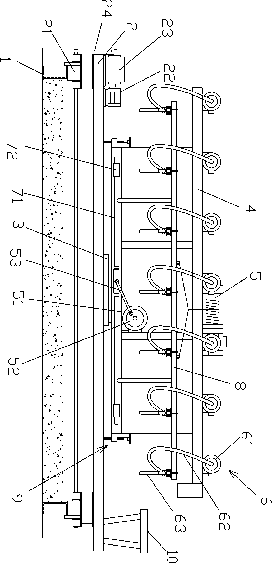
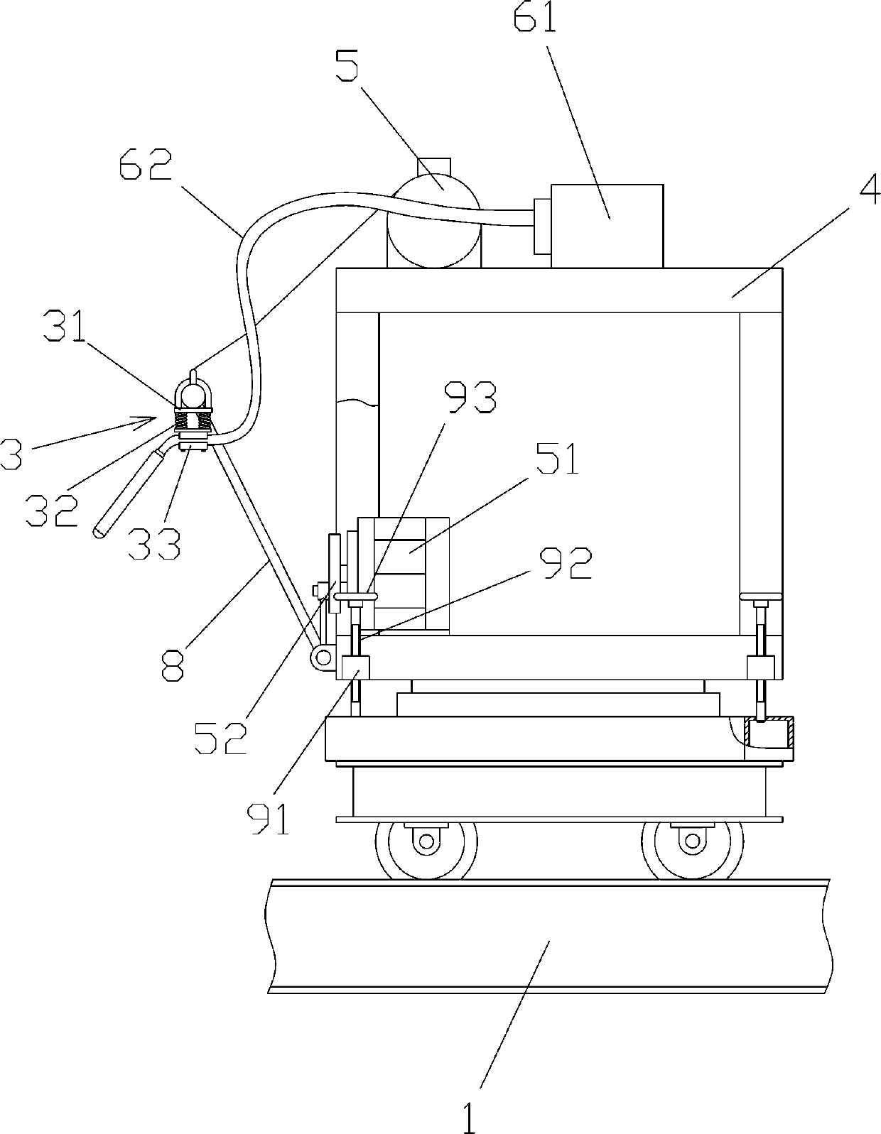
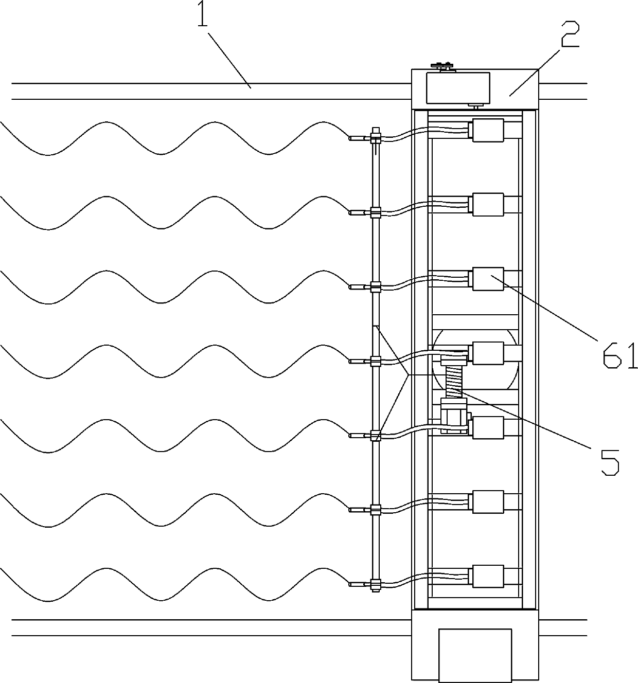
[0022] Such as Figures 1 to 3 As shown, a concrete vibrating device includes a bottom frame 2, on which a roller 21 and a travel motor 22 are installed, and the travel motor 22 is connected to the roller 21 through a speed reducer 23 and a sprocket transmission mechanism 24, and also includes Frame 4 and overturning frame 8, the middle part of frame 4 is connected with bottom frame 2 through slewing bearing 3, the lower end of overturning frame 8 is hinged on the lower end of frame 4, hoist machine 5 and multiple plug-in vibrators 6 are installed on frame 4, plug-in type Vibrator 6 comprises vibrating motor 61, flexible shaft tube 62 and vibrating pen 63, vibrating motor 61 is installed on the frame 4, vibrating pen 63 one end is connected overturn frame 8 upper ends by damping device 3, hoist 5 wire ropes connect overturn frame 8.

[0023] In the present invention:

[0024] The walking motor 22 can adopt the YE2-100 three-phase asynchronous motor produced by "Linqing Xingye...


PUM


Abstract

Provided are a concrete vibrating device and method. The concrete vibrating device comprise a bottom frame, wherein rollers and a walking motor are installed on the bottom frame, and the walking motoris connected with the rollers through a speed reducer and a chain wheel transmission mechanism in a transmission way. The concrete vibrating device further comprises a frame and a turnover frame, wherein the middle portion of the frame is connected with the bottom frame through a rotary bearing, the lower end of the turnover frame is hinged to the lower end of the frame, a winch and a plurality of inserted vibrators are installed on the frame, and the inserted vibrators comprise vibrating motors, flexible shaft pipes and vibrating pens. The vibration motors are installed on the frame, one endof each vibration pen is connected with the upper end of the turnover frame through a vibration damping device, and a steel wire rope of the winch is connected with the turnover frame. The inventionaims to decrease the installation quantity of the inserted vibrators and meanwhile reducing the equipment manufacturing cost.

Description

technical field [0001] The invention relates to a concrete vibrating device and method. Background technique [0002] Vibration refers to the process of vibrating and compacting the concrete mixture unloaded into the pouring bin, which can improve the strength of concrete and ensure the quality of concrete components. The vibrating rod is commonly used for vibrating. Due to the large area inside, using a vibrating rod for vibrating requires a lot of labor, and the production efficiency is low, and the labor intensity of the workers is high. Moreover, due to manual vibration, the quality of the vibration cannot be achieved. Guaranteed. In order to solve this problem, the prior art mostly uses a vibrating machine, for example: the patent No. is "CN 204919284 U" and the name is "a vibrating device"; the patent number is "CN 201614541 U" and the name is "a kind of road Surface Concrete High-Frequency Vibration Machine", these two vibrating devices are not suitable for vibratin...

Claims


Application Information

Patent Timeline
Patent Type & Authority Applications(China)
IPC IPC(8): E01C19/38
Inventor 刘元
Owner 湖北乾奥建设工程有限公司
Why Eureka
Try Eureka