Signal processing method and device
A signal processing and signal technology, applied in the application field of communication technology, can solve the problems of large amount of calculation and low decoding efficiency
- Summary
- Abstract
- Description
- Claims
- Application Information
AI Technical Summary
Problems solved by technology
Method used
Image
Examples
Embodiment 1
[0035] According to an embodiment of the present invention, an embodiment of a decoding method is provided. It should be noted that the steps shown in the flowcharts of the accompanying drawings can be executed in a computer system such as a set of computer-executable instructions, and, although in The flowcharts show a logical order, but in some cases the steps shown or described may be performed in an order different from that shown or described herein.
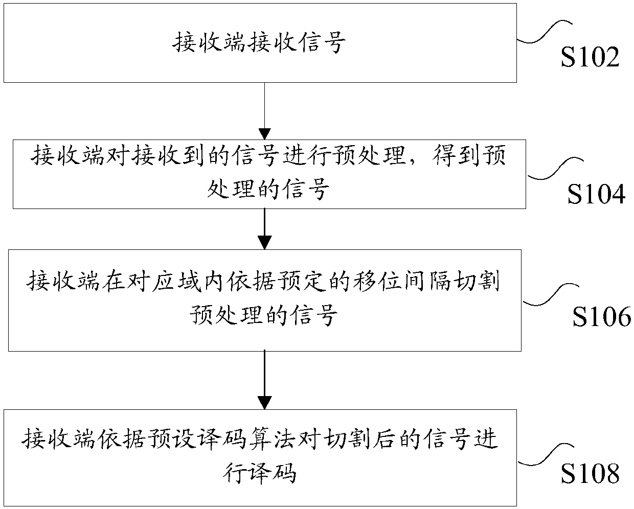
[0036] figure 1 is a schematic flowchart of a signal processing method at a receiving end according to an embodiment of the present invention, such as figure 1 As shown, at the receiving end side, the signal processing method includes the following steps under the OvTDM system:
[0037] Step S102, the receiving end receives the signal;
[0038] Step S104, the receiving end preprocesses the received signal to obtain a preprocessed signal; specific preprocessing may include operations such as synchronization, channel estima...
Embodiment 2
[0142] Figure 11 is a schematic flowchart of a signal processing method at a sending end according to an embodiment of the present invention, as shown in Figure 11 As shown, at the sender side, the signal processing method at the sender includes the following steps:
[0143] Step S1102, the transmitting end generates an envelope signal in the modulation domain according to the design parameters;
[0144]Step S1104, the transmitting end shifts the envelope signal in the modulation domain according to a predetermined displacement interval according to the number of overlapping multiplexing, to obtain each shifted envelope signal in the modulation domain;
[0145] Step S1106, the transmitting end multiplies the symbols in the sequence to be modulated with their corresponding shifted envelope signals to obtain the modulated envelope signal in the modulation domain;
[0146] Step S1108, the transmitting end superimposes the modulation envelope signal in the modulation domain to...
Embodiment 3
[0148] Figure 12 is a schematic structural diagram of a receiving device according to an embodiment of the present invention, such as Figure 12 As shown, on the receiver side, the device includes:
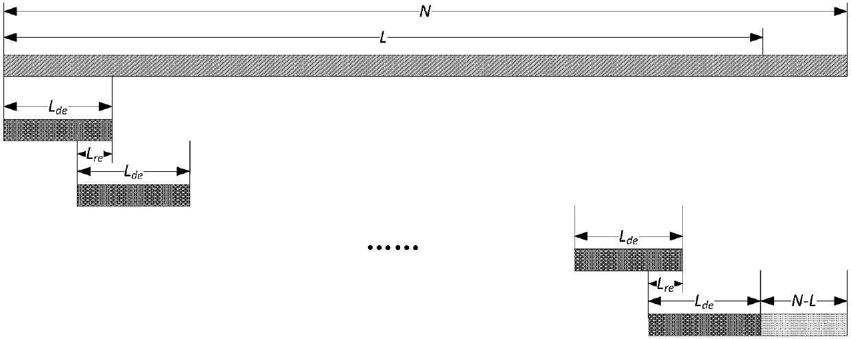
[0149] The receiving module 1202 is used to receive the signal; the preprocessing module 1204 is used to preprocess the received signal to obtain a preprocessed signal; the cutting module 1206 is used to cut the preprocessed signal according to a predetermined shift interval in the corresponding domain signal; a decoding module 1208, used to decode the cut signal according to a preset decoding algorithm; wherein, the decoding module 1208 includes: a length determination unit 12081, used to determine the sliding window length and the sliding window according to the number of system overlaps The length of the overlapping portion; the first acquisition unit 12082 is used to determine the encoded original sequence length of the signal according to the length of the sliding window an...
PUM
 Abstract
Description
Claims
Application Information
 - R&D
- Intellectual Property
- Life Sciences
- Materials
- Tech Scout
- Unparalleled Data Quality
- Higher Quality Content
- 60% Fewer Hallucinations
Browse by: Latest US Patents, China's latest patents, Technical Efficacy Thesaurus, Application Domain, Technology Topic, Popular Technical Reports.
© 2025 PatSnap. All rights reserved.Legal|Privacy policy|Modern Slavery Act Transparency Statement|Sitemap|About US| Contact US: help@patsnap.com


