Self-adjusting dust remover

A dust collector and self-adjusting technology, applied in chemical instruments and methods, dispersed particle separation, combined devices, etc., can solve the problems of poor dust removal effect and low utilization rate of dust collectors, and achieve the effect of absorbing tiny dust.

Active Publication Date: 2019-06-04
广州博泰机械科技有限公司
View PDF3 Cites 6 Cited by
  • Summary
  • Abstract
  • Description
  • Claims
  • Application Information

AI Technical Summary

Problems solved by technology

[0005] The purpose of the present invention is to provide a self-regulating dust collector with good dust removal effect and high utilization rate for the problems of low utilization rate and poor dust removal effect of existing dust collectors

Method used


Image

  • Self-adjusting dust remover
  • Self-adjusting dust remover
  • Self-adjusting dust remover

Examples


Embodiment 1

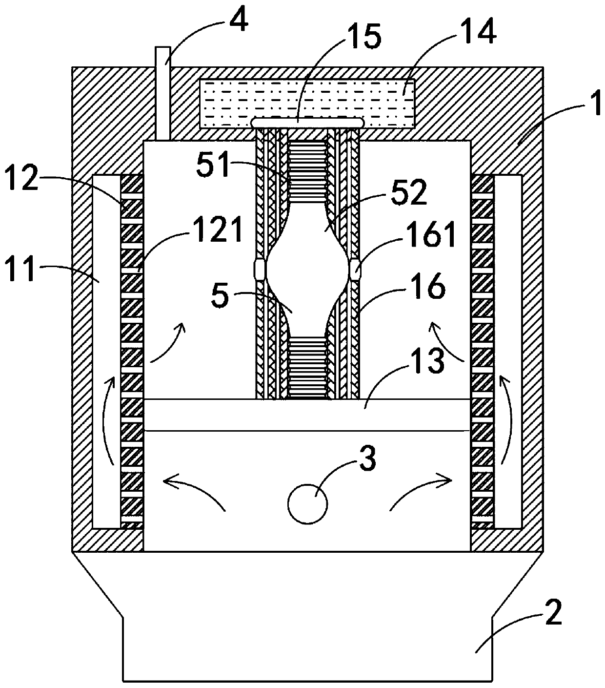
[0032] Such as Figure 1-2 As shown, a self-regulating dust collector includes a housing 1 and an ash hopper 2. An air intake pipe 3 and an exhaust pipe 4 are fixedly connected to the side wall of the housing 1. It should be noted that the air intake pipe 3 is close to the ash hopper 2, the exhaust pipe 4 is set on the top of the housing 1, and the housing 1 is equipped with:

[0033] Annular groove 11, the annular groove 11 is arranged on the inner side wall of the housing 1; dust filter plate 12, the dust filter plate 12 is fixedly installed in the annular groove 11, there is a gap between the dust filter plate 12 and the annular groove 11, and the array distribution on the dust filter plate 12 There are a plurality of dust filter holes 121; a sealing plate 13, and the edge of the sealing plate 13 is in sliding and sealing connection with the side wall of the dust filter plate 12; After the body 1, the large particles of smoke will directly settle into the ash hopper 2.

...

Embodiment 2

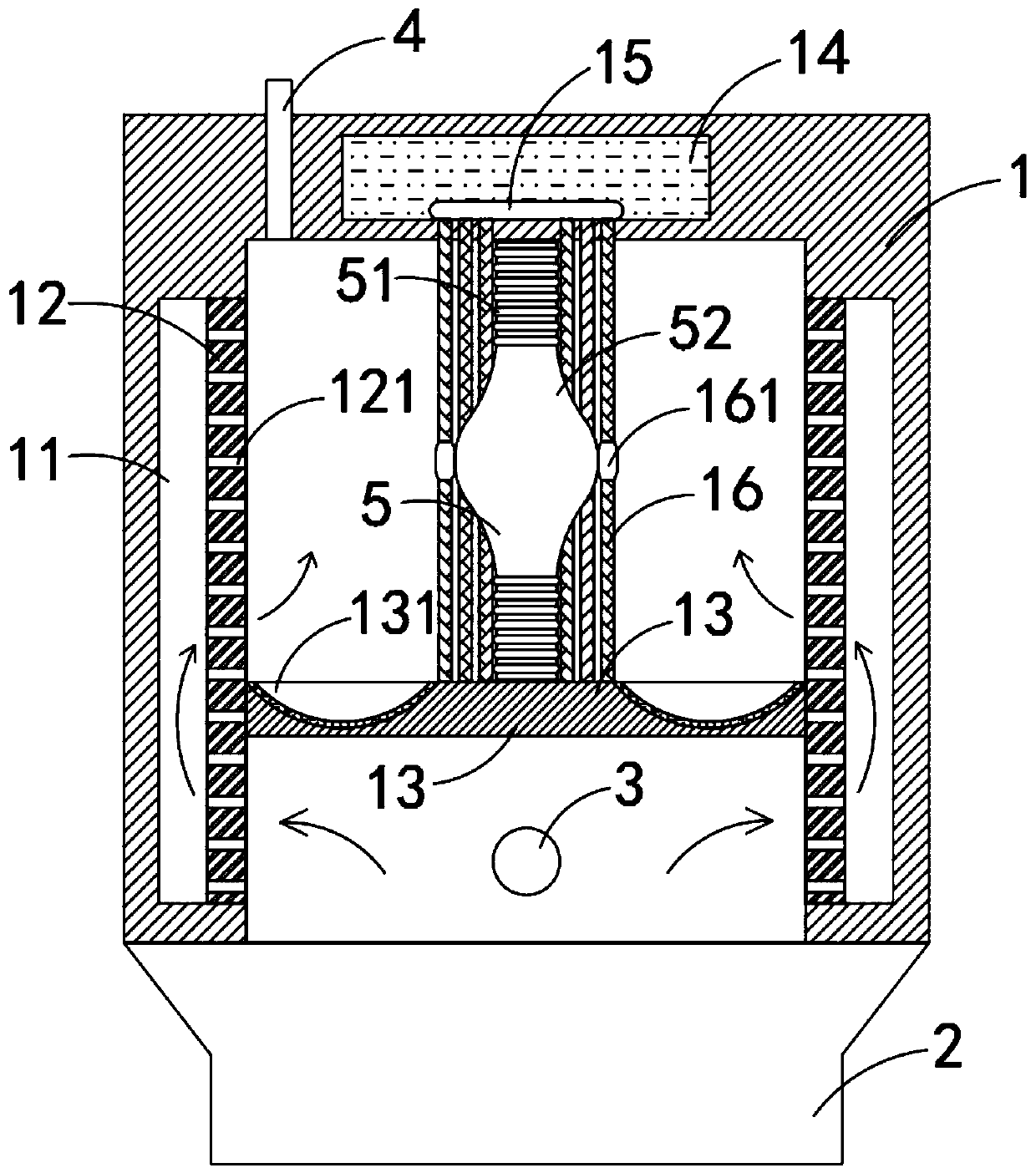
[0042] Such as image 3 As shown, the difference between this embodiment and Embodiment 1 is that the sealing plate 13 is made of a denser material such as a metal material, and the upper end of the sealing plate 13 is provided with a dust removal groove 131, and the dust removal groove 131 is a 52 is provided with an annular groove, and an adsorption layer is arranged in the dust removal groove 131.

[0043] In this embodiment, after the dust is filtered, the sealing plate 13 will fall vertically under the action of its own gravity and make the water-absorbing strip 16 straighten instantly, thereby throwing off the small water droplets adsorbed on the water-absorbing strip 16 Into the dust removal groove 131, it can facilitate the later cleaning, and can also improve the water absorption capacity of the water absorption strip 16, thereby enhancing the dust removal effect of the dust collector.


PUM


Abstract

The invention belongs to the field of dust removers, and particularly relates to a self-adjusting dust remover. The self-adjusting dust remover comprises a shell and a dust collecting hopper, and an air inlet pipe and an exhaust pipe are fixedly connected to the side wall of the shell. The interior of the shell is provided with: an annular groove formed in the shell and formed in the inner side wall of the shell; a dust filtering plate fixedly installed in the annular groove, wherein a plurality of dust filtering holes are distributed in the dust filtering plate in an array mode; a sealing plate, of which the edge is in sliding and sealing connection with the side wall of the dust filtering plate; a liquid storage cavity formed in the upper part of the shell and internally filled with a cleaning agent; a water absorption ring fixedly connected to the inner bottom surface of the liquid storage cavity; a plurality of water absorption strips with upper ends penetrating through the shell and fixedly connected with the water absorption ring and lower ends fixedly connected with the upper end of the sealing plate; and a deformation mechanism which is arranged among the plurality of waterabsorption strips and comprises the following components as the specification. Dynamic adjustment of the dust filter can be achieved according to the air inflow, so that the utilization rate of the dust filter can be greatly increased and the dust adsorption effect is improved.

Description

technical field [0001] The invention belongs to the field of dust collectors, in particular to a self-regulating dust collector. Background technique [0002] The function of the dust collector is to separate the dust from the flue gas, so as to avoid the air pollution caused by the direct discharge of the flue gas. [0003] The internal structure of the existing dust collector is fixed, and the dust removal capacity is also certain. However, in the actual dust removal process, the airflow of the intake air is always in a state of change, and the rated flow rate cannot be maintained, so that dust removal cannot be performed according to the specific air flow rate, resulting in the dust removal of the dust collector. The utilization rate is low; in addition, because dust is easy to attach to the air inlet of the filter hole, over time, the dust removal effect of the dust collector will become poor. [0004] For this reason, we propose a self-regulating dust collector to solv...

Claims


Application Information

Patent Timeline
Patent Type & Authority Applications(China)
IPC IPC(8): B01D50/00
Inventor 林亿彬
Owner 广州博泰机械科技有限公司
Why Eureka
Try Eureka