
Numerical control machine tool for wood processing

A CNC machine tool and wood technology, which is applied to wood processing equipment, processing machines for manufacturing flat surfaces, fine planers, etc., can solve the problems of hidden dangers for the safety of operators, high labor intensity of operators, and low planing efficiency. , to achieve the effects of improved precision, high planing efficiency and ingenious structure

Inactive Publication Date: 2019-06-04
廉江市信宇家居有限公司
View PDF3 Cites 3 Cited by
  • Summary
  • Abstract
  • Description
  • Claims
  • Application Information

AI Technical Summary

Problems solved by technology

[0002] A woodworking planer is a woodworking machine tool that uses a rotary or fixed planer to process the plane or forming surface of wood. The woodworking planer is used to plan a reference plane of the workpiece. After consulting the information, the existing ordinary woodworking planer uses a motor to drive the planer shaft at a high speed. Rotate, hand press the wood workpiece along the guide plate and send it from the back table to the planer shaft of the front table. The front table is lower than the back table and the height of the two is adjustable. The function of planing the plane, its planing efficiency is low, the accuracy is poor, the labor intensity of the operator is high, and the operator presses the wood workpiece with bare hands and moves towards the planer, which buryes hidden dangers for the safety of the operator. For this reason, the inventor designed An automatic feeding reciprocating woodworking planer with ingenious structure, simple principle, high degree of automation, high planing efficiency, high forming plane precision, and high safety factor

Method used


Image

  • Numerical control machine tool for wood processing
  • Numerical control machine tool for wood processing
  • Numerical control machine tool for wood processing

Examples


Embodiment Construction

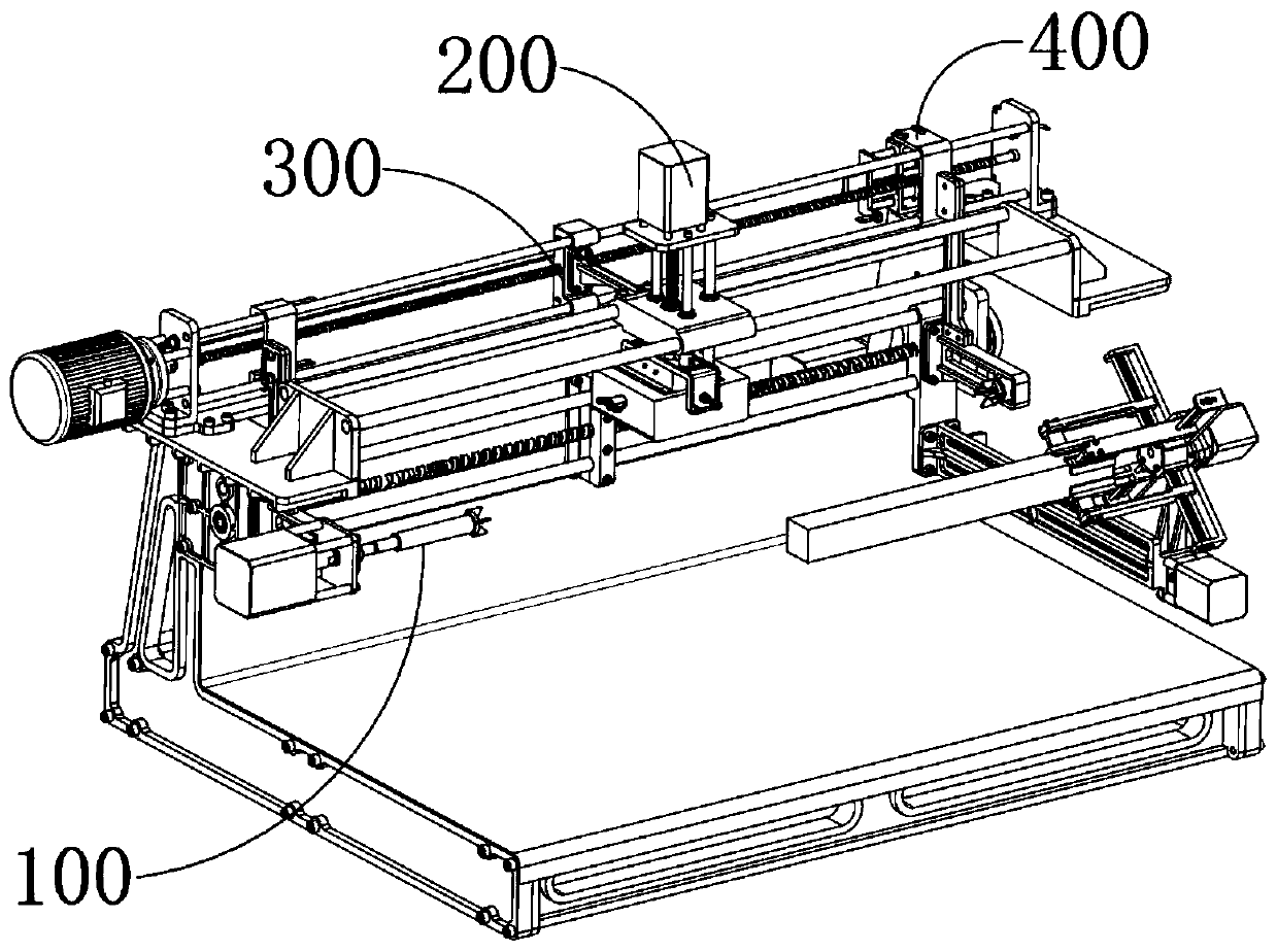
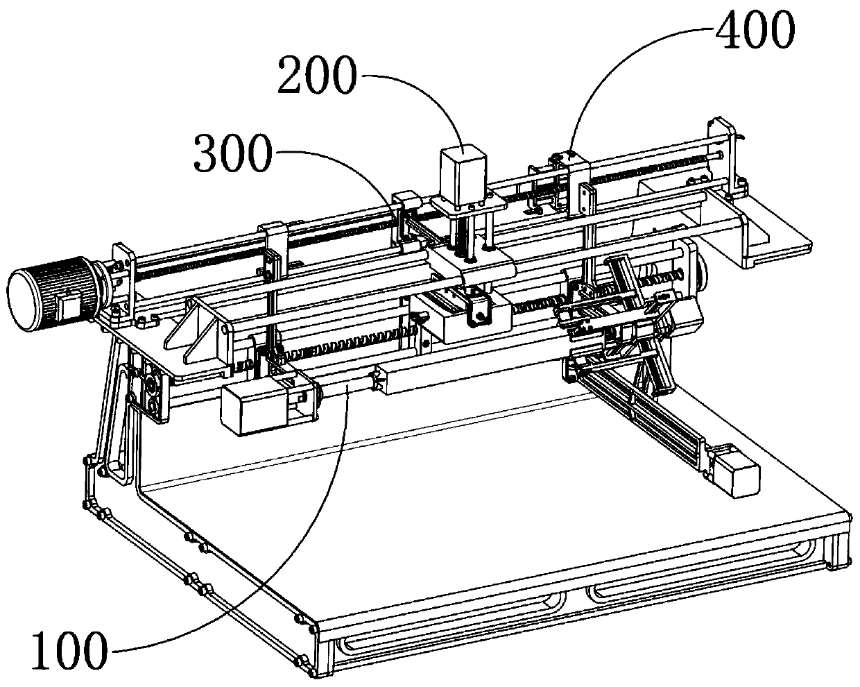
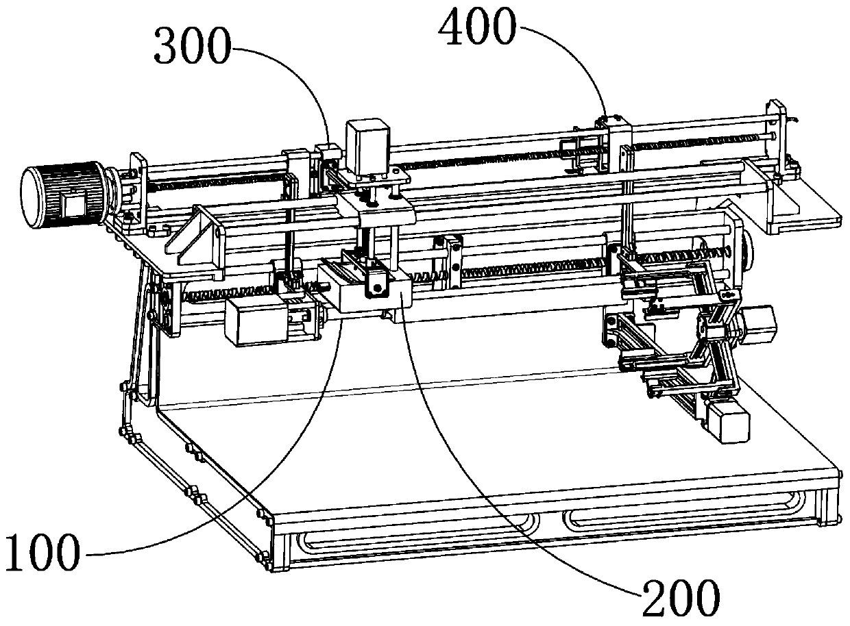
[0056] A numerical control machine tool for wood processing, which includes a clamping device 100 for clamping a long strip of wood workpiece, and a planing device 200 for reciprocating planing of the wood workpiece clamped by the clamping device 100 , the traveling driving device 300 for driving the planing device 200 to move in one direction along the planing direction, and the retraction control for releasing the driving of the planing device 200 by the traveling driving device 300 while pulling the planing device 200 to reset in a single reverse movement The device 400 , the planing device 200 is arranged above the clamping device 100 , the traveling driving device 300 is arranged on one side of the planing device 200 , and the retraction control device 400 is arranged on the traveling driving device 300 .

[0057] The process for the user to plan the plane of the wood workpiece is to clamp the wood workpiece on the clamping device 100 for fixing, and place the side to be p...


PUM


Abstract

The invention provides a numerical control machine tool for wood processing. The numerical control machine tool comprises a clamping device for clamping a long-strip-shaped wood workpiece, a planing device used for conducting reciprocating plane planing on the wood workpiece clamped by the clamping device, an advancing driving device used for driving the planing device to unidirectionally move inthe planing direction, and a retracement control device used for reliving driving of the driving device on the planing device and meanwhile pulling the planing device to move unidirectionally and oppositely to be reset, the planing device is arranged above the clamping device, the advancing driving device is arranged on one side of the planing device, the retracement control device is arranged onthe advancing driving device, the clamping device comprises a clamping mechanism used for clamping the wood workpiece and a feeding mechanism used for moving the wood workpiece into the clamping mechanism to be clamped, the planing device comprises a lifting planer tool mechanism and a reciprocating mechanism used for driving the lifting planer tool mechanism to move in a reciprocating mode in thedirection parallel to the length direction of a tool body, and the lifting planer tool mechanism is located above the clamping device.

Description

technical field [0001] The invention relates to the technical field of wood processing equipment, in particular to a numerically controlled machine tool for wood processing. Background technique [0002] A woodworking planer is a woodworking machine tool that uses a rotary or fixed planer to process the plane or forming surface of wood. The woodworking planer is used to plan a reference plane of the workpiece. After consulting the information, the existing ordinary woodworking planer uses a motor to drive the planer shaft at a high speed. Rotate, hand press the wood workpiece along the guide plate and send it from the back table to the planer shaft of the front table. The front table is lower than the back table and the height of the two is adjustable. The function of planing the plane, its planing efficiency is low, the accuracy is poor, the labor intensity of the operator is high, and the operator presses the wood workpiece with bare hands and moves towards the planer, whi...

Claims


Application Information

Patent Timeline
IPC IPC(8): B27C1/00B27C1/02B27C1/14
Inventor 张红梅
Owner 廉江市信宇家居有限公司
Learn More