
Reversing valve for plastic melt

A reversing valve and melt technology, which is applied in the field of reversing valves for plastic melts, can solve the problems of inability to discharge, blockage of pipes, and confusion, and achieves the effects of convenient use, easy cleaning and simple structure

Pending Publication Date: 2019-06-04
WEIHAI RISING SUN FILTER CO LTD
View PDF7 Cites 2 Cited by
  • Summary
  • Abstract
  • Description
  • Claims
  • Application Information

AI Technical Summary

Problems solved by technology

[0003] However, when the existing reversing valve switches the flow direction of the molten material for pipeline maintenance, a certain amount of molten material impurities will remain in the original discharge hole, which cannot be discharged. After a long time, the remaining molten material will be Coking or hardening occurs, and after the pipeline is repaired, switch the reversing valve to the original working state, and the coked or hardened melt in the original discharge hole will be washed into the pipeline, and then mixed in the better quality melt , thereby affecting the production quality of the product, and at the same time, it may cause the subsequent pipeline to continue to be blocked

Method used


Image

  • Reversing valve for plastic melt
  • Reversing valve for plastic melt
  • Reversing valve for plastic melt

Examples


Embodiment Construction

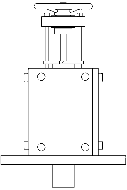
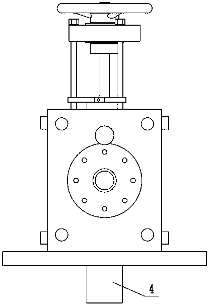
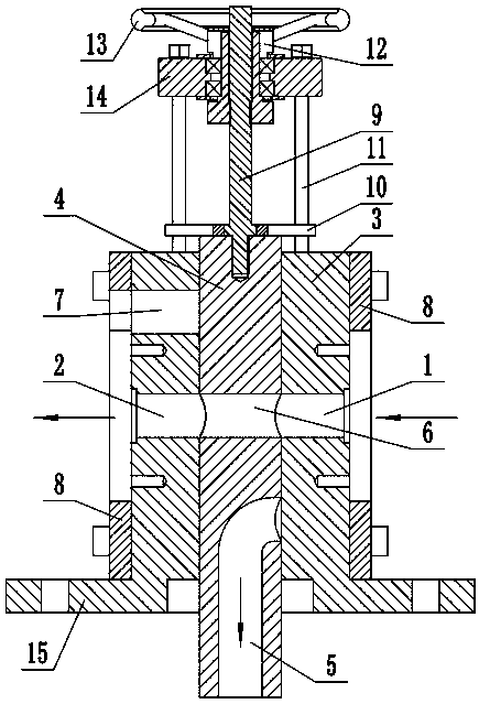
[0024] Referring to the accompanying drawings, the reversing valve for plastic melt includes a valve body 3 with a feed hole 1 on the right and a discharge hole 2 on the left, wherein the feed hole 1 and the discharge hole 2 are circular Shaped hole and coaxial arrangement, in addition, the middle part of valve body 3 is also provided with the valve cavity that penetrates valve body up and down and communicates with feed hole 1 and discharge hole 2, and this valve cavity is also preferably round hole shape; In addition, valve cavity The middle slide is equipped with a spool 4 that can slide up and down. Of course, the spool 4 is also in the shape of a vertical column; in addition, the top of the valve body 3 is equipped with a driving device that can drive the spool 4 to move up and down. The device can be driven manually or electrically, such as Figure 1-Figure 6 As shown, the preferred driving device is a manual driving mode. Therefore, the driving device includes a valve r...


PUM


Abstract

The invention discloses a reversing valve for a plastic melt. The reversing valve comprises a valve body, a feeding hole is formed in the right side of the valve body, and a discharging hole is formedin the left side of the valve body; a vertically-through valve cavity communicating with the feeding hole and the discharging hole is formed in the middle of the valve body; a valve element capable of sliding up and down is slidably assembled in the valve cavity, and a driving device capable of driving the valve element to move up and down is mounted at the top of the valve body; a lower flow channel is formed in the lower end of the valve element, and an upper flow channel located in the upper part of the lower flow channel is further formed in the valve element; after the valve element slides to the upper-limit position, an upper opening of the lower flow channel communicates with the feeding hole; after the valve element slides to the lower-limit position, the upper flow channel communicates with the feeding hole and the discharging hole; and a clearing hole is further formed in the left side part of the valve body, and the clearing hole can be kept coaxially communicate with the upper flow channel after the valve element slides to the upper-limit position. The reversing valve for the plastic melt is simple in structure and convenient to use, it can be ensured that equipment works without stopping, and residue melting stock in the valve body can further be cleared conveniently.

Description

technical field [0001] The invention relates to a reversing valve for plastic melt. Background technique [0002] In the production equipment of plastic products such as films, it is necessary to ensure that the plastic melt flows in the pipeline at all times, and at the same time, ensure that the melt has a certain temperature. After the shutdown, the melt will undergo high-temperature coking or low-temperature hardening or plastic change in the pipeline. Therefore, it is necessary to reduce the downtime and frequency of the equipment as much as possible; at the same time, it is also necessary to connect multiple reversing valves in series on the melt pipeline. The reversing valve usually has one feed hole and more than two discharge holes. The purpose of the directional valve is to change the flow direction of the molten material in the pipeline according to the needs of use, so that the molten material can be discharged from the pipeline; for example, when the pipeline at...

Claims


Application Information

Patent Timeline
Patent Type & Authority Applications(China)
IPC IPC(8): F16K11/07F16K49/00F16K27/04
Inventor 吴孟龙
Owner WEIHAI RISING SUN FILTER CO LTD
Learn More