Rooftop wind turbine flow improvements

A turbine and vertical flow technology, applied in the direction of wind turbines, installation/support configuration of wind turbines, combination of wind turbines, etc., can solve problems such as no solution, degradation of turbine unbalanced force, low power, etc.

Active Publication Date: 2019-06-04
丹尼尔・法伯
View PDF8 Cites 0 Cited by
  • Summary
  • Abstract
  • Description
  • Claims
  • Application Information

AI Technical Summary

Problems solved by technology

[0004] Previous studies have noted the problem of wind turbulence on roofs, but most have looked to roofs as a solution for avoiding obstructions, usually on the roof surface: “As a rule of thumb, turbines should be at least 150 m (500 ft) Any obstacle in range up to 9 meters (30 feet):" One reference identifies the problem with no solution: "Worse, all obstacles, trees, other structures, and even the house itself, cause wind turbulent flow
This has the disadvantage of less power from the tilt vector, and faster degradation of the turbo imbalance forces, so it doesn't really solve the problem
From the cited references it is clear that these solutions were not thought of even by experts in said field

Method used


Image

  • Rooftop wind turbine flow improvements
  • Rooftop wind turbine flow improvements
  • Rooftop wind turbine flow improvements

Examples


Embodiment Construction

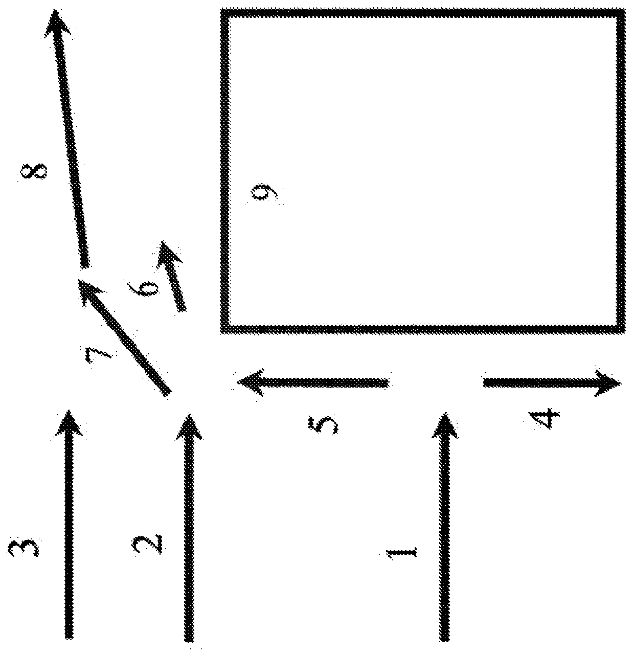
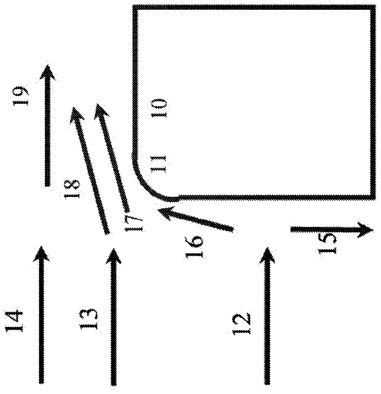
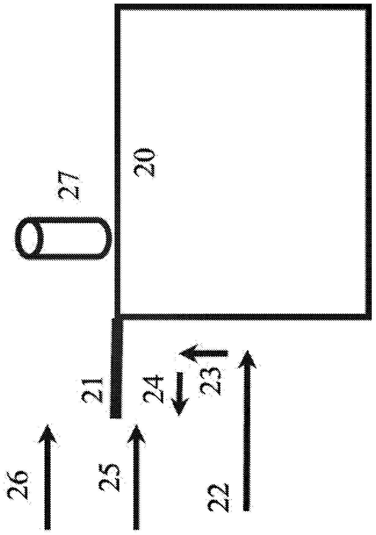
[0053] The invention makes the wind power of the roof more practical and solves the problem of wind deformation caused by buildings on the roof.

[0054] Definition: For the sake of specific language, a roof is called a platform in the claims, meaning a flat surface higher than its surroundings, and the side of the building as a vertical surface, even if it is not exactly at 90 degrees. This was done to make the principles general enough to be applicable to many situations, such as underwater turbines for underwater platforms or buildings with atypical shapes. Downstream is the same as downwind; it means the area further in the direction of flow.

[0055] The principles and operation of manufacturing a roof-contained wind turbine by removing obstructions and turbulence in accordance with the present invention may be better understood with reference to the drawings and accompanying descriptions.

[0056] The present invention solves the problem of buildings creating flow obsta...


PUM


Abstract

One of the challenges of rooftop wind turbines is that the building causes turbulence and updrafts and can create a blockage to the wind at rooftop level. That means lower speed and higher turbulencewind hitting the turbine and less power output. Prior art solutions consisted of elevating the blades of rooftop turbines or making the updraft hit the blades. Creating structures that separate the turbulence of the air below roof level from the oncoming and higher velocity linear wind above roof level, where the turbine is located, can decrease slowing of the rooftop level wind stream and enablethe blades to be placed closer to roof level, thereby saving construction costs and roof weight. It is ideal to combine these improvements with a vertical axis wind turbine.

Description

[0001] Cross-referencing related application documents [0002] This application claims the benefit of U.S. Provisional Patent Application No. 62 / 384,732, filed September 8, 2016. technical field [0003] The present invention relates to a method of influencing wind motion on a roof so that the building interferes less with the power generation of the roof turbine. Of course this can be applied, and by said application is meant any similar environment, but also underwater turbines and seascapes. Background technique [0004] Previous studies have noted the problem of wind turbulence on roofs, but most have looked to roofs as a solution for avoiding obstructions, usually on the roof surface: “As a rule of thumb, turbines should be at least 150 m (500 ft) Any obstacle in range up to 9 meters (30 feet):" One reference identifies the problem with no solution: "Worse, all obstacles, trees, other structures, and even the house itself, cause wind turbines.” (http: / / www.engineeri...

Claims


Application Information

Patent Timeline
Patent Type & Authority Applications(China)
IPC IPC(8): F03D9/45E04D13/15
CPCF03D9/45E04D13/00F05B2240/13F05B2240/211F05B2240/9112F03D13/20Y02B10/30Y02E10/728E04D13/15Y02E10/72
Inventor 丹尼尔·法伯
Owner 丹尼尔・法伯
Why Eureka
Try Eureka