
Heat-dissipating arrangement and method for the production thereof

A technology of equipment and heat conduction elements, which is applied in the manufacturing field of the preamble, can solve space problems and other problems, and achieve the effect of simple and cheap method and good heat conduction

Active Publication Date: 2019-06-04
ZF FRIEDRICHSHAFEN AG
View PDF30 Cites 0 Cited by
  • Summary
  • Abstract
  • Description
  • Claims
  • Application Information

AI Technical Summary

Problems solved by technology

This can cause space issues when installing the equipment

Method used


Image

  • Heat-dissipating arrangement and method for the production thereof
  • Heat-dissipating arrangement and method for the production thereof
  • Heat-dissipating arrangement and method for the production thereof

Examples


Embodiment Construction

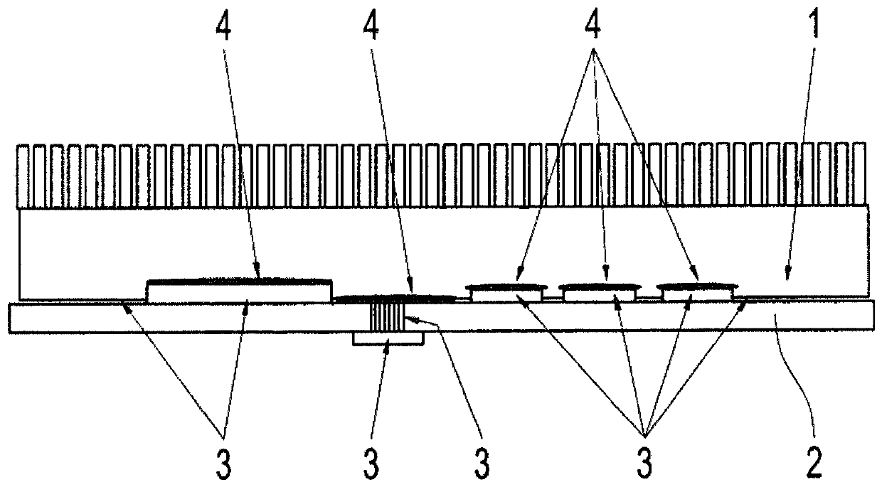
[0024] For better thermal connection or heat dissipation between the heat sink and the components arranged on the printed circuit board, the method according to the invention makes it possible to dispense with intermediate layers. For better heat-conducting connection of the cooling body, the heat-conducting element can be integrated directly into the cooling body, or it can be integrated as a separate component during manufacture. The heat-conducting element has a special structure and is preferably at least partially filled with a heat-conducting medium, hereinafter only referred to as medium. The medium can here be present with or without circulation in the closed heat-conducting element or be in contact with the respective component, ie the heat-conducting element has a direction along the component(s) on which it is arranged Open structure. Thermally conductive elements can also be purchased or manufactured as separate components to be mounted on one or more components a...


PUM


Abstract

Disclosed is a heat-dissipating arrangement, wherein the heat-dissipating arrangement has at least one power module which has a printed circuit board (2) having components (3) to be cooled arranged thereon, and at least one heat sink (1) arranged on the printed circuit board (2) and over the components (3) to be cooled. On at least one of the components (3) to be cooled there is at least one heat-conducting element (100) which has a predefined structure extending from the printed circuit board (2) away from the printed circuit board into the heat sink (1), the heat-conducting element (100) containing a heat-dissipating medium in the interior thereof.

Description

technical field [0001] The invention relates to a heat-discharging device according to the preamble of claim 1 , and to a manufacturing method according to the preamble of claim 7 . Background technique [0002] Heat-conducting elements such as heat sinks are used in power electronics and control units for cooling various components, for example components or structures on circuit boards. Due to tolerances and existing surface properties, direct contact of the heat sink to the component is not optimal for heat transfer. Therefore, in the currently known heat dissipation strategies, it is necessary to introduce a gap-filled and thermally conductive layer for better thermal connection, as in figure 1 as shown in reference number 4. Such a gap-filling and heat-conducting layer 4 can be a heat-conducting paste or a so-called caulk which is arranged on the corresponding component 3 , that is to say a component, structure or process which is arranged, for example, on the circuit...

Claims


Application Information

Patent Timeline
Patent Type & Authority Applications(China)
IPC IPC(8): H05K7/20F28D15/02
CPCH05K7/20336H05K7/20936F28D15/0233F28F2255/18H01L23/427B33Y80/00
Inventor 马蒂亚斯·霍伊斯尔曼马库斯·鲍恩芬德赫尔曼·约瑟夫·罗宾库尔特·米歇尔
Owner ZF FRIEDRICHSHAFEN AG
Learn More