Guide wire device capable of adjusting bending

The invention relates to a wire guide device and a technology of bending adjustment, which is applied in the field of guide wire devices and adjustable bending guide wire devices, and can solve the problems of inability to quickly install and disassemble a bending handle, complicated structure of the bending handle, poor twist control of the guide wire, and the like. Achieve the effect of saving operation time, less parts, and eliminating torsional clearance

Pending Publication Date: 2019-06-07
HANGZHOU WEIQIANG MEDICAL TECH CO LTD
View PDF0 Cites 2 Cited by
  • Summary
  • Abstract
  • Description
  • Claims
  • Application Information

AI Technical Summary

Problems solved by technology

[0005] The technical problem to be solved by the present invention is that the proximal main body of the core wire in the prior art will also bend during the bending adjustment process, the guide wire has poor twist control, the bending adjustment handle has a complicated structure, and the operation is inconvenient, and the adjustment is difficult. The curved handle cannot be quickly installed and disassembled with the guide wire body. Provide a method that can prevent the proximal body of the core wire from bending during the bending process. The guide wire has better torque control and uses a detachable handle and the guide wire body. An adjustable curved guide wire device that can be quickly separated, has a simple structure, and is easy to operate

Method used


Image

  • Guide wire device capable of adjusting bending
  • Guide wire device capable of adjusting bending
  • Guide wire device capable of adjusting bending

Examples


Embodiment 1

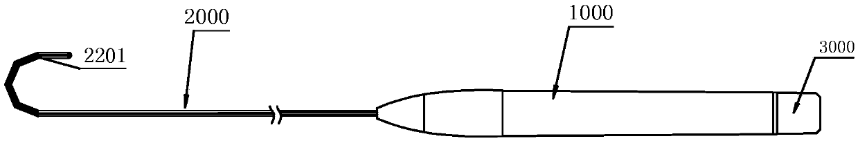
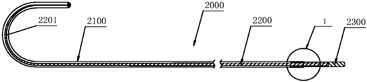
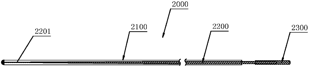
[0052] Embodiment 1, as Figure 1-7 As shown, an adjustable bending guide wire device includes a guide wire main body 2000 , and the guide wire main body 2000 includes a hollow outer guide wire 2100 and a core wire 2200 worn in the lumen of the outer guide wire 2100 . The distal end of the outer guide wire 2100 is fixedly connected to the distal end of the core wire 2200 . The distal end of the core wire 2200 is provided with a distal portion 2101 . The distal end portion 2101 of the core wire 2200 is curved in a free state. The adjustable bend guide wire device further includes a bend adjustment mechanism 1000 for adjusting the degree of bending of the distal end of the guide wire main body 2000 and a guide wire locking mechanism 3000 for locking the proximal end of the core wire 2200 . The proximal end of the core wire 2200 passes through the outer guide wire 2100 and is detachably and fixedly connected with the guide wire locking mechanism 3000 . The bending adjustment m...

Embodiment 2

[0073] Embodiment 2, this embodiment is an improvement on the basis of Embodiment 1.

[0074] Such as Figure 8-9 As shown, an adjustable curved guide wire device includes a guide wire main body 2000 whose distal end is bent in a free state. The guide wire body 2000 includes a hollow outer guide wire 2100 and a core wire 2200 worn in the lumen of the outer guide wire 2100 . The distal end of the outer guide wire 2100 is fixedly connected to the distal end of the core wire 2200 . The adjustable bend guide wire device further includes a bend adjustment mechanism 1000 for adjusting the degree of bending of the distal end of the guide wire main body 2000 and a guide wire locking mechanism 3000 for locking the proximal end of the core wire 2200 . The proximal end of the core wire 2200 passes through the outer guide wire 2100 and is detachably and fixedly connected with the guide wire locking mechanism 3000 . The bending adjustment mechanism 1000 is movably sleeved on the proxima...

Embodiment 3

[0078] Embodiment 3, this embodiment is an improvement on the basis of Embodiment 1.

[0079] Such as Figure 10-14 As shown, an adjustable curved guide wire device includes a guide wire main body 2000 whose distal end is bent in a free state. The guide wire body 2000 includes a hollow outer guide wire 2100 and a core wire 2200 worn in the lumen of the outer guide wire 2100 . The distal end of the outer guide wire 2100 is fixedly connected to the distal end of the core wire 2200 . The device also includes a bending adjustment mechanism 1000 for adjusting the bending degree of the distal end of the guide wire main body 2000 and a guide wire locking mechanism 3000 for locking the proximal end of the core wire 2200 . The proximal end of the core wire 2200 passes through the outer guide wire 2100 and is detachably and fixedly connected with the guide wire locking mechanism 3000 . The bending adjustment mechanism 1000 is movably sleeved on the proximal end of the guide wire main...


PUM


Abstract

The invention discloses a guide wire device capable of adjusting bending. The device includes a guide wire main body. The guide wire main body includes a hollow outer guide wire and a core wire passing through the cavity of the outer guide wire. An end head of the far-end of the outer guide wire is fixedly connected to an end head of the far-end of the core wire. A far-end part which is shaped into a curved shape is arranged on the far-end of the core wire. The far-end of the guide wire main body is curved in a free state. The device also includes a bending adjusting mechanism used for adjusting a bending degree of the far-end of the guide wire main body and a guide wire locking mechanism used for locking the near-end of the core wire. The near-end of the core wire extends out of the outerguide wire and is detachably and fixedly connected to the guide wire locking mechanism. The bending adjusting mechanism is movably connected to the near-end of the guide wire main body and drives thenear-end of the outer guide wire to move axially relative to the near-end of the core wire. The guide wire locking mechanism is detachably fixed to the near-end of the bending adjusting mechanism. The invention provides the guide wire device capable of adjusting bending which can detach a handle from the guide wire main body, is rapid in separation and simple in operation.

Description

technical field [0001] The invention belongs to the technical field of medical devices, and relates to a guide wire device, in particular to an adjustable bend guide wire device. Background technique [0002] A guide wire, also known as a guide wire or guide wire, is one of the main tools for percutaneous catheterization. The guide wire has the function of guiding and supporting the catheter, and can guide medical devices such as catheters and delivery sheaths into blood vessels and other human body cavities, and smoothly reach the designated position or lesion. However, due to the inherent curvature of the blood vessel and the complex anatomical structure of the human body, the guide wire may be bent and coiled in the lumen, thereby affecting its passability. [0003] An adjustable bending fishing guide wire disclosed in the prior art, its bending control end is composed of a handle base, a handle twist rod, an adjustment wire and a metal adjustment ring, through the screw...

Claims


Application Information

Patent Timeline
Patent Type & Authority Applications(China)
IPC IPC(8): A61M25/09
Inventor 李阳潘湘斌张庭超徐澧
Owner HANGZHOU WEIQIANG MEDICAL TECH CO LTD
Why Eureka
Try Eureka