Glass fiber crushing equipment and waste wire processing method

A technology of glass fiber and crushing equipment, which is applied in the direction of grain processing, etc., can solve the problems of large manpower and material resources consumption, easy winding, difficulty in recycling and crushing waste silk, etc., and achieve the effect of improving cutting effect and avoiding winding

Active Publication Date: 2019-06-07
旌德县源远新材料有限公司
View PDF8 Cites 7 Cited by
  • Summary
  • Abstract
  • Description
  • Claims
  • Application Information

AI Technical Summary

Problems solved by technology

For glass fiber waste, it can be dug and buried deep, but this treatment method consumes a lot of manpower and material resources, and will affect the environment
[0003] According to energy recycling and environmental protection requirements, the waste silk produced in glass fiber production is required to be recycled and reused, but the waste silk is in the shape of slender strips, and the waste silk is easy to form agglomerates, and the existing settings cannot effectively Recycling and crushing the clumped waste silk, and at the same time, the filamentary waste silk is also easily entangled on the rotating parts of the crushing equipment, which makes it difficult to recycle and crush the waste silk

Method used


Image

  • Glass fiber crushing equipment and waste wire processing method
  • Glass fiber crushing equipment and waste wire processing method
  • Glass fiber crushing equipment and waste wire processing method

Examples


Embodiment 2

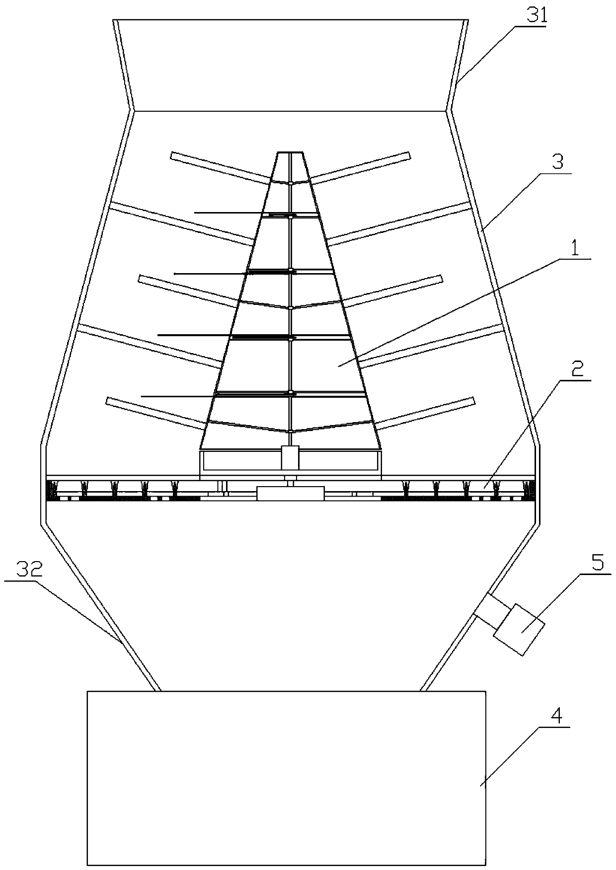
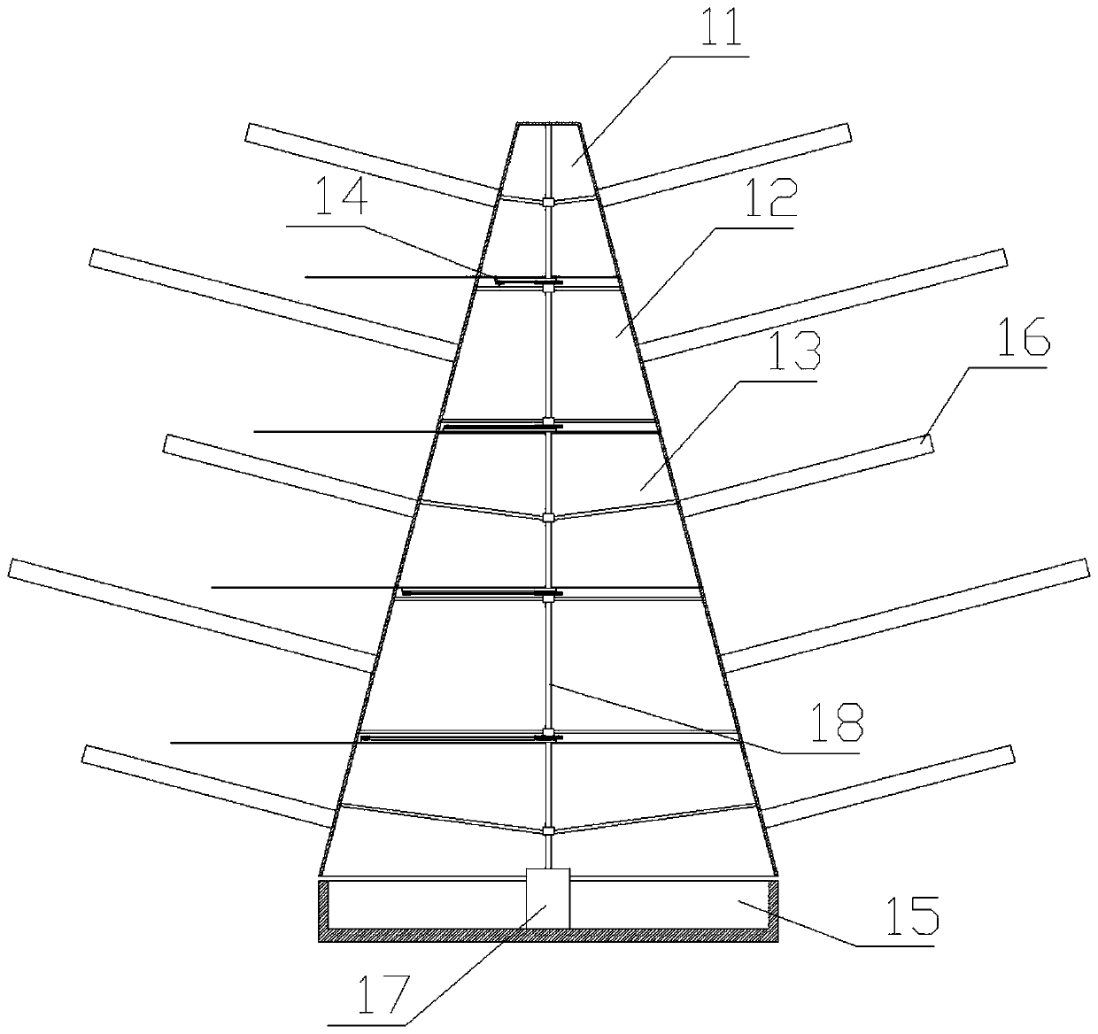
[0038] like figure 2 as shown, figure 2It is a schematic structural view of the first cutting device; the first cutting device 1 includes a top cover 11, several fixed parts 12, several rotating parts 13, a cutting assembly 14 and a base 15; the fixed part 12 and the rotating part 13 are arranged alternately between the top cover 11 and the base 15; the first cutting device 1 is set in a circular truncated shape as a whole, and the cross section of the first cutting device 1 gradually becomes larger from top to bottom; The distance between the outer surface of the first cutting device 1 and the inner surface of the cylinder body 3 is consistent; the outer surfaces of the top cover 11, the fixed part 12, and the rotating part 13 are uniformly provided with a number of push rods 16, The dial rod 16 is cylindrical, and the fixed part 12 is fixedly connected with the inner surface of the cylinder body 3 through the dial rod 16; the dial on the top cover 11 and the rotating part...

Embodiment 3

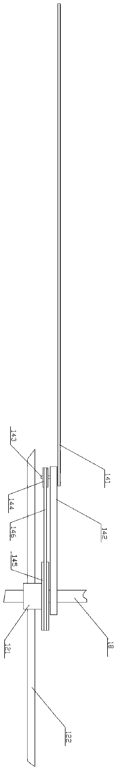
[0044] like image 3 as shown, image 3 It is a schematic structural view of the cutting assembly; the cutting assembly 14 includes a cutting knife 141 and a connecting rod 142, and the two ends of the connecting rod 142 are respectively connected to the rotating shaft 18 and the cutting knife 141, and the cutting knife 141 and The connecting position of the connecting rod 142 is provided with a connecting shaft, and the connecting shaft is fixedly connected with the cutting knife 141. The connecting rod 142 is provided with a connecting hole corresponding to the connecting shaft, and the connecting shaft 143 is arranged on the In the connection hole, the cutting knife 141 and the connecting rod 142 can rotate relatively around the connecting shaft 143; the connecting rod 142 is fixedly connected to the rotating shaft 18; the cutting knife 141 has a blade for Cut waste.

[0045] The connecting shaft 143 is also provided with a transmission wheel 144; the rotating shaft 18 is...

Embodiment 4

[0051] In order to ensure that the cutting knife 141 effectively cuts the waste silk between the fixed part 12 and the rotating part 13, the cutting knife 141 needs to be on the corresponding part of the fixed part 12 and the rotating part 13. Stretch out between the shifting rods 16 to cut the waste silk wound on the two described shifting rods 16; To achieve the best cutting effect. Therefore, the relationship needs to be satisfied:

[0052]

[0053] Wherein, R is the radius of the fixed wheel 145 ; r is the radius of the transmission wheel 144 ; θ is the angle between adjacent shift rods 16 on the same fixed part 12 or the rotating part 13 .

[0054] On the basis of the third embodiment, due to the influence of the length of the connecting rod 142 and the length setting of the cutting knife 141, the working sections where the cutting knife 141 actually stretches out and realizes cutting are all different; Distribute the quantity of described cutting knife 141, all can ...


PUM


Abstract

The invention discloses glass fiber crushing equipment and a waste wire processing method. The glass fiber crushing equipment comprises a cutting device, the cutting device is arranged in a cylinder of the glass fiber crushing equipment, the cylinder is in a round table shape with the small upper and lower ends and the large middle, a feeding opening is formed in the upper end of the cylinder, a discharging pipe is arranged at the lower end of the cylinder and connected with a crushing device, and small-size fiber glass after cutting by the cutting device is guided out through the dischargingpipe and enters the crushing device to be crushed. According to the glass fiber crushing equipment, a fixed disc and a rotating disc rotate relatively, the waste wire falls on a cutting piece, under the rotation of the rotating disc, the waste wire of the cutting piece and the cutting piece move relatively, and the cutting of the waste wire by the cutting piece is achieved accordingly.

Description

technical field [0001] The invention relates to the technical field of glass fiber processing, in particular to a glass fiber crushing equipment and a waste silk processing method. Background technique [0002] my country is the world's largest producer of glass fiber, but the ensuing waste problem is unavoidable. A large amount of glass fiber waste is produced every year. The composition of the glass fiber waste used is the same as that of the finished glass fiber, which belongs to inorganic Silicate materials in non-metallic materials are not degradable in nature. For glass fiber waste, it can be dug and buried deep, but this treatment method consumes a lot of manpower and material resources, and will affect the environment. [0003] According to energy recycling and environmental protection requirements, the waste silk produced in glass fiber production is required to be recycled and reused, but the waste silk is in the shape of slender strips, and the waste silk is easy ...

Claims


Application Information

Patent Timeline
Patent Type & Authority Applications(China)
IPC IPC(8): B02C21/00B02C18/12B02C18/18B02C18/16B02C23/16B02C23/24B02C18/24
CPCB02C18/0084B02C18/12B02C18/18B02C18/2216B02C23/16B02C2023/165B02C2201/06
Inventor 孙雪源谷学荣
Owner 旌德县源远新材料有限公司
Why Eureka
Try Eureka