Fan coil magnetic machine and fan coil magnetic assembly method thereof

A fan and magnetic machine technology, applied in the field of magnetic winding machines, can solve the problems of difficult to effectively control and improve product quality stability, difficult product quality, and low production efficiency

Pending Publication Date: 2019-06-07
HANGZHOU TAISHANG INTELLIGENT EQUIP CO LTD
View PDF0 Cites 7 Cited by
  • Summary
  • Abstract
  • Description
  • Claims
  • Application Information

AI Technical Summary

Problems solved by technology

[0003] The present invention solves the problem that existing notebook computer heat dissipation fans coil magnetic assembly requires more operators and labor costs, and the production efficiency is low. At the same time, it is difficult to better and effectively control the quality of the final product, and it is difficult to effectively control the stability

Method used


Image

  • Fan coil magnetic machine and fan coil magnetic assembly method thereof
  • Fan coil magnetic machine and fan coil magnetic assembly method thereof
  • Fan coil magnetic machine and fan coil magnetic assembly method thereof

Examples


Embodiment 1

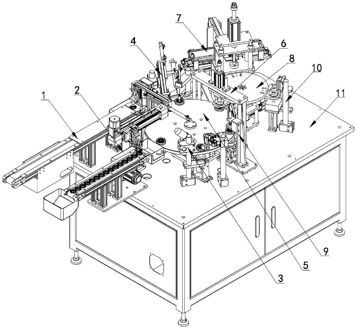
[0073] Figure 1 to Figure 43 In the shown embodiment, a fan winding machine includes a winding frame 11, and also includes a feeding mechanism 1, a discharging mechanism 2, an oil lock spraying and testing mechanism 3, and a coating mechanism installed on the winding frame. Glue mechanism 4, indexing plate for assembly 5, magnetic ring press-in mechanism 6, magnetic coiling mechanism 7, indexing plate for magnetic coiling 8, height detection mechanism 9 and magnetic ring magnetizing mechanism 10, the inner end and outlet of the feeding mechanism Between the inner ends of the feeding mechanism, there are oil-locking spraying and testing mechanisms, glue coating mechanisms, indexing plates for assembly, magnetic ring pressing mechanisms, magnetic coiling mechanisms, indexing plates for magnetic coiling, height detection mechanisms and magnetic ring charging. Magnetic mechanism, oil lock spraying and detection mechanism, glue application mechanism, magnetic ring pressing mechani...

Embodiment 2

[0093] A magnetic winding assembly method for a fan magnetic winding machine, comprising the following assembly steps

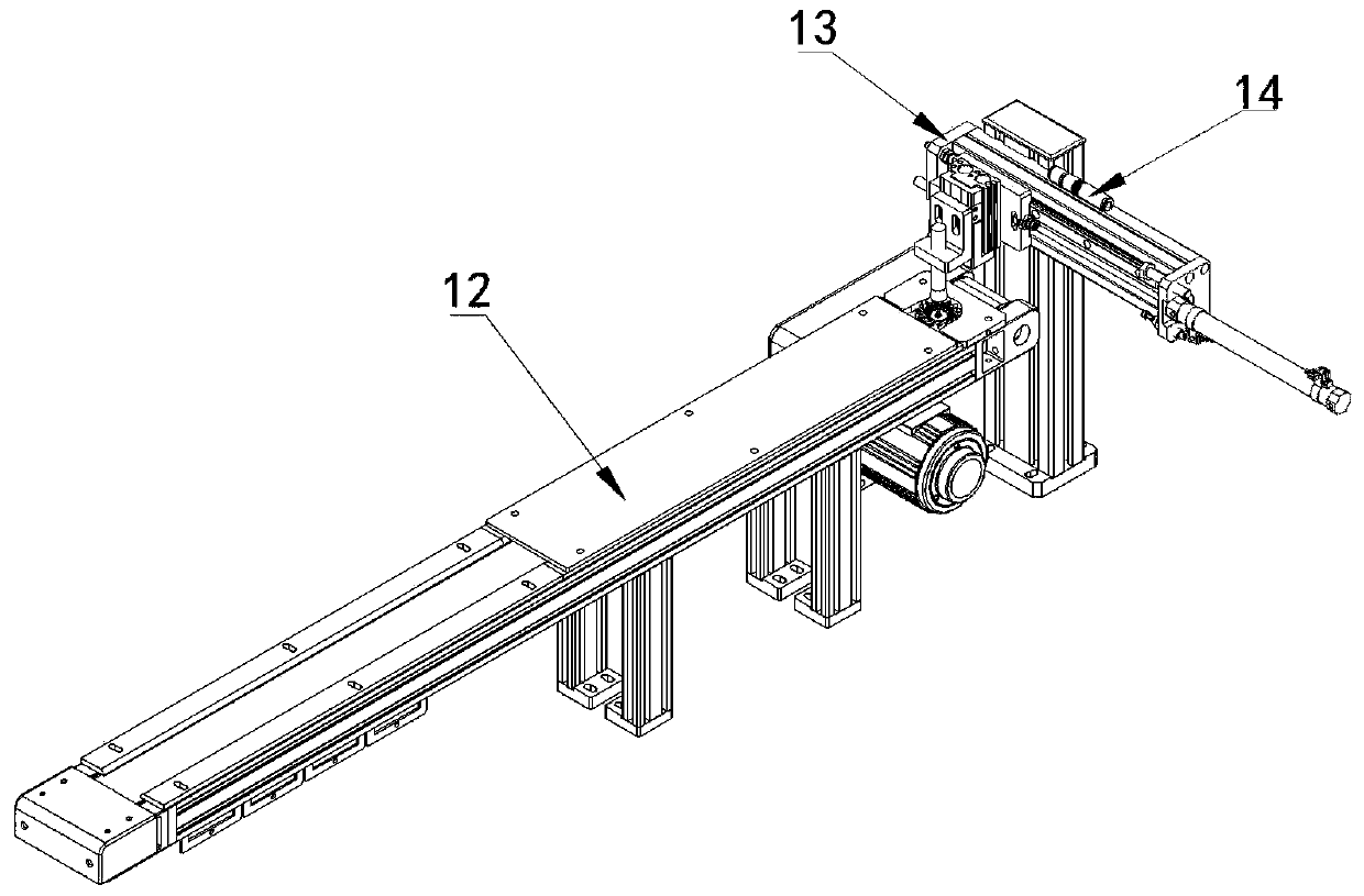
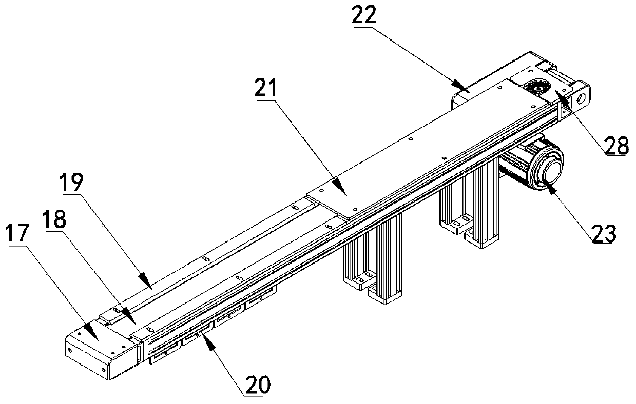
[0094] a. Place the fan blade casing on the feeding belt line provided by the feeding mechanism described in Example 1, and the conveying drive drives the fan blade casing to reach the feeding traverse module set by the feeding mechanism;

[0095] b The reclaiming cylinder in the feed traverse module moves down, the vacuum nozzle moves, and after sucking the fan blade casing, the reclaim cylinder rises, and the traverse cylinder in the feed traverse module moves to move to the fan blade casing When reaching above the accompanying jig set on the assembly index plate described in Example 1, the reclaiming cylinder descends to the accompanying jig, the vacuum nozzle releases the fan blade shell, then the reclaiming cylinder rises, and the traverse cylinder moves return to original position;

[0096] c The iron ring induction mechanism described in embodiment 1 ...


PUM


Abstract

The invention discloses a fan coil magnetic machine and a fan coil magnetic assembly method thereof. A feeding mechanism, a discharging mechanism, an oil locking spraying and detecting mechanism, a gluing mechanism, a magnetic ring pressing-in mechanism and a height detecting mechanism which can assemble a fan blade shell and a magnetic ring on the assembly index plate are distributed outside theassembly index plate, a coil magnetic mechanism and a magnetic ring magnetizing mechanism are arranged on the outer side of a coil magnetic index plate, the magnetic ring pressing-in mechanism is arranged between the assembly index plate and the magnetic coil index plate which are adjacent, and the magnetic ring pressing-in mechanism is used for pressing the magnetic ring on the magnetic coil index plate to fan blades on the assembly index plate. The coil magnetic mechanism is used for winding a magnetic strip on the magnetic coil index plate into the magnetic ring for assembly, the magnetic ring magnetizing mechanism magnetizes the magnetic ring, the oil locking spraying and detecting mechanism performs oil locking spraying and detecting on a fan, and the gluing mechanism glues the fan blade shell. The production efficiency of the notebook computer cooling fan coil magnetic assembly is improved, and the labor use cost and the labor management cost are reduced.

Description

technical field [0001] The invention relates to a magnetic winding machine, in particular to a cooling fan used in a notebook computer. Background technique [0002] The cooling fans used in existing notebook computers basically use outsourced accessories, and the external supplier of notebook cooling fans assembles the cooling fan magnetically, mainly through manual operations to complete the production, during which operators need to complete points separately. Multi-step manual operations such as glue, magnetic strip rolling, magnetizing, and magnetizing, etc., and then assembled with the fan, and in each step, manual inspection is required to control the production quality, which requires more operators and labor costs. Production The efficiency is low, and at the same time it is difficult to better and effectively control the quality of the final product, and the stability of product quality is difficult to be effectively controlled and improved. Contents of the inven...

Claims


Application Information

Patent Timeline
IPC IPC(8): B07C5/08B23P19/027H01F13/00
Inventor 徐正方徐镓宽
Owner HANGZHOU TAISHANG INTELLIGENT EQUIP CO LTD
Why Eureka
Try Eureka