Punching device for square end plate

A punching device and square technology, applied in the field of punching devices, can solve problems such as punching of end plates, and achieve the effect of highlighting substantive features

Inactive Publication Date: 2019-06-07
广东毅马集团有限公司 +10
View PDF3 Cites 3 Cited by
  • Summary
  • Abstract
  • Description
  • Claims
  • Application Information

AI Technical Summary

Problems solved by technology

[0002] At present, the existing punching device punches the end plate one by one, and the several punching holes obtained after processing are either arranged in a circle or in a straight line. In this way, such a punching device is not suitable for other punching holes. Hole arrangement required end plate for punching

Method used


Image

  • Punching device for square end plate
  • Punching device for square end plate
  • Punching device for square end plate

Examples


Embodiment Construction

[0020] The features of the present invention and other relevant features are described in further detail below through the embodiments, so as to facilitate the understanding of those skilled in the art:

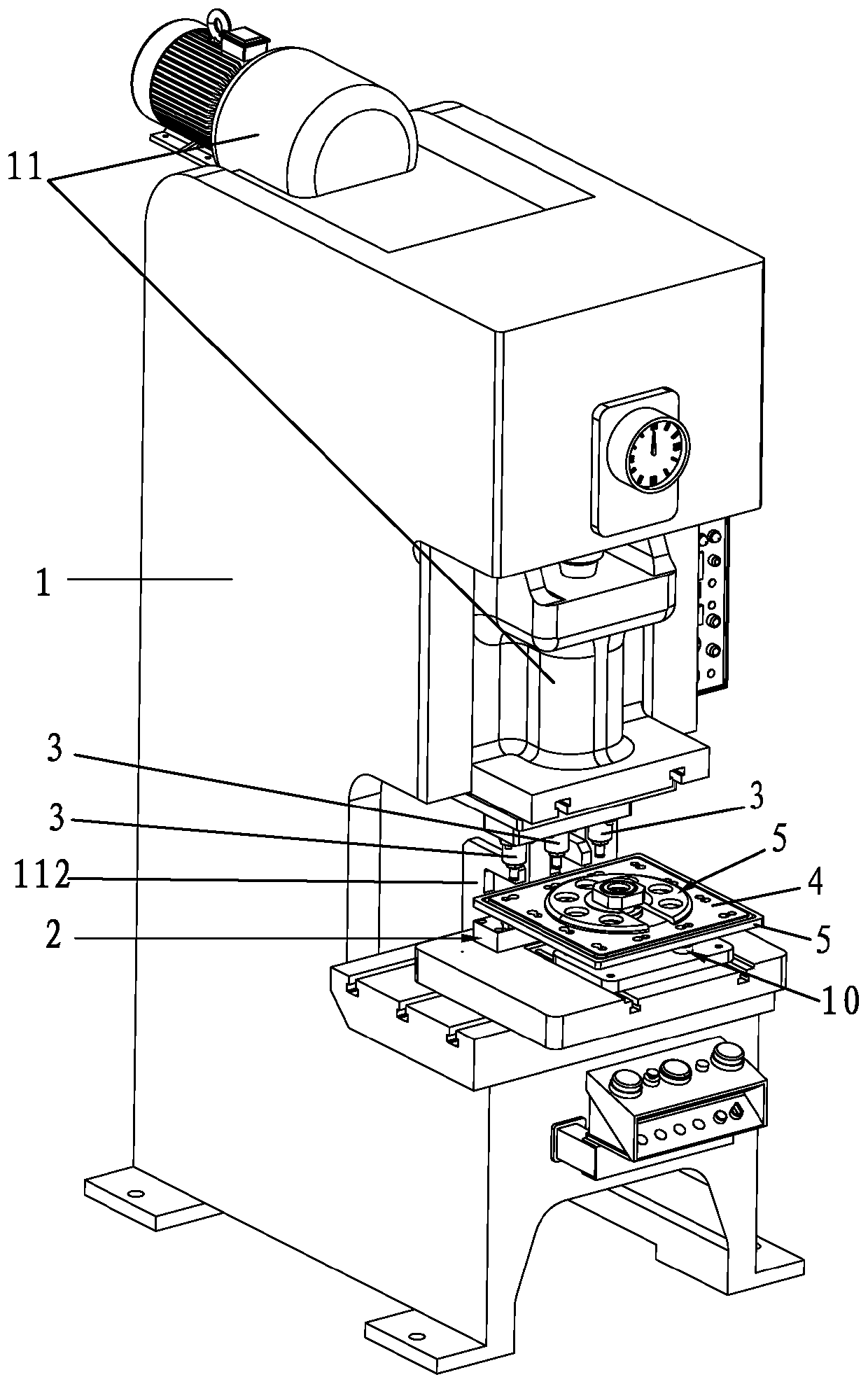
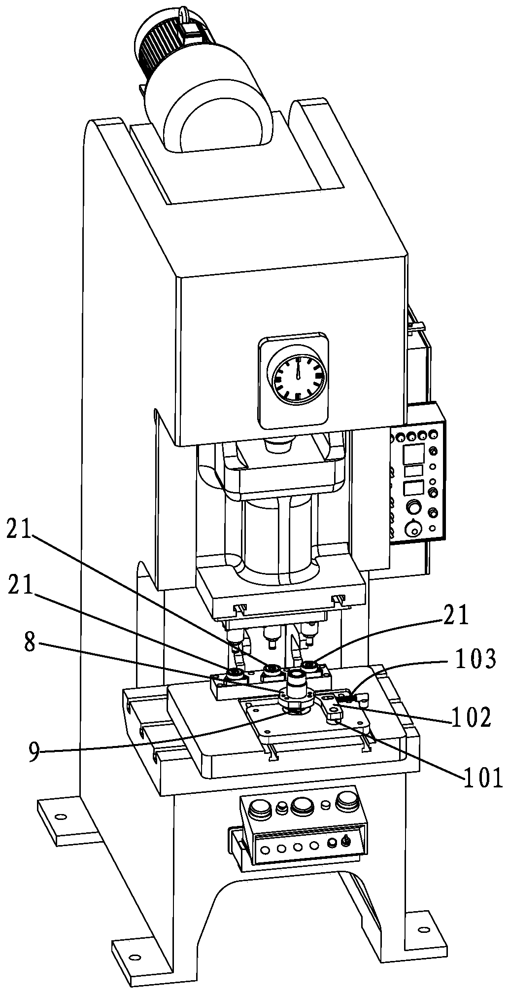
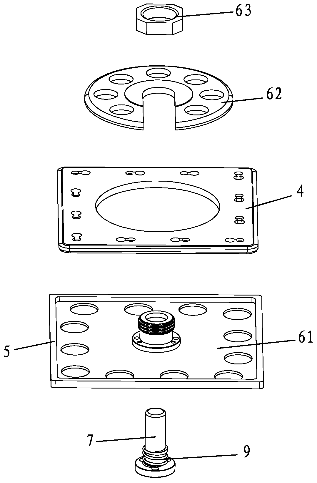
[0021] like Figure 1 to Figure 5 As shown, a punching device for a square end plate includes a bracket 1, the bracket 1 is provided with a lower die hole seat 2, a stamping head 3 positioned above the lower die hole seat 2, and a The square end plate 4 to be punched is supported on the tray 5 between the lower punch hole seat 2 and the punch head 3, and the lower punch hole seat 2 is provided with a lower hole corresponding to the position of the punch head 3. Die holes 21, the tray 5 is provided with a first positioning and fixing mechanism 6 for positioning and fixing the square end plate 4, the tray 5 is mounted on the bracket 1 by rotating the first vertical shaft 7, The lower end of the tray 5 is fixedly connected with a quadrant indexing plate 8 which rotates synchron...


PUM


Abstract

The invention discloses a punching device for a square end plate. The square end plate is positioned and fixed to a tray through an arranged first positioning and fixing mechanism, so that the squareend plate, the tray and a quartering indexing plate synchronously rotate or move up and down together; a bracket is also provided with a positioning component matched with the quartering indexing plate, and therefore when the tray is rotated, the tray can be conveniently controlled to rotate by 90 degrees at a time, the square end plate just turns over one side, rotation is conveniently carried out after punching is conveniently carried out at the current side of the square end plate to make the next side of the square end plate just reach the position below a punching head, the positions of punched holes in the sides of the square end plate are better ensured, the punched holes are conveniently punched in all sides of the square end plate, and the outstanding substantive features and significant progress are achieved.

Description

technical field [0001] The invention relates to a punching device for square end plates. Background technique [0002] At present, the existing punching device punches the end plate one by one, and the number of punched holes obtained after processing is either arranged in a circle or in a straight line. In this way, such a punching device is not suitable for other punching holes. The end plate required by the hole arrangement is punched. [0003] Therefore, how to overcome the above existing defects has become an important issue to be solved urgently by those skilled in the art. Contents of the invention [0004] The present invention overcomes the disadvantages of the above technologies and provides a punching device for square end plates. [0005] To achieve the above object, the present invention adopts the following technical solutions: [0006] A punching device for a square end plate, comprising a support 1, the support 1 is provided with a lower die hole seat 2,...

Claims


Application Information

Patent Timeline
IPC IPC(8): B21D28/34B21D28/36B21D28/26
Inventor 刘静
Owner 广东毅马集团有限公司
Why Eureka
Try Eureka