Rail suspension intelligent inspection robot system
What is Al technical title?
Al technical title is built by PatSnap Al team. It summarizes the technical point description of the patent document.
A robot system, intelligent inspection technology, applied in the direction of manipulators, manufacturing tools, etc., can solve the problems of inspection fatigue, inaccurate walking, unstable equipment operation, etc., to avoid human error, compact structure, simple structure effect.
Active Publication Date: 2019-06-07
JIANGSU FRONTIER ELECTRIC TECH +2
View PDF14 Cites 25 Cited by
Summary
Abstract
Description
Claims
Application Information
AI Technical Summary
This helps you quickly interpret patents by identifying the three key elements:
Problems solved by technology
Method used
Benefits of technology
Problems solved by technology
[0002] At present, in the computer rooms or power distribution stations of some important equipment, manual guards are arranged, and the operation status of the equipment is inspected regularly. In such repetitive work day after day, it is easy to form a kind of inspection fatigue, which makes people in a In the state of numbness, during the inspection, there are omissions in the early signals and symptoms of unstable work of some equipment. When equipment failure occurs, it will often cause heavy property losses, and even major accidents of personal casualties.
Therefore, people thought of using robots instead of manual duty to improve the problems in manual duty. However, there are still some shortcomings in the existing inspection robots on the market. It can walk on a straight track or an arc track with a large radius. In order to solve the problems of slipping and inaccurate walking, some brake mechanisms are added, which makes the mechanical structure of the robot more complicated and the weight increased. major issues
Method used
Image
Click on the blue label to locate the original text in one second.
Reading with bidirectional positioning of images and text.
Examples
Embodiment Construction
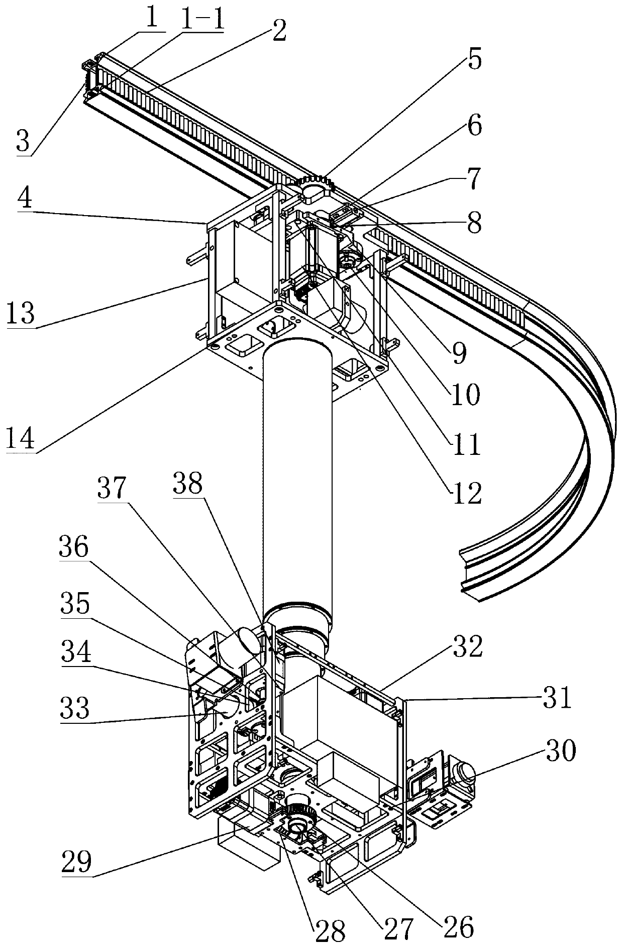
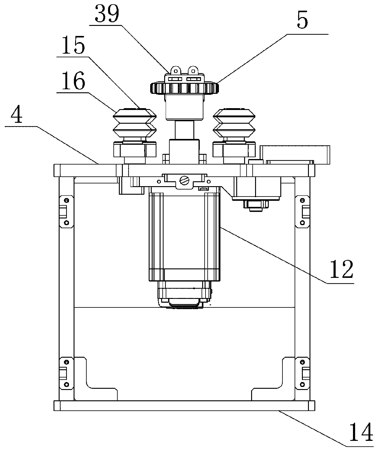
[0052] Reference attached Figure 1-14 , A rail suspension intelligent inspection robot system includes a V-shaped groove track 1, a walking trolley, a lifting mechanism and a camera rotating pan / tilt.
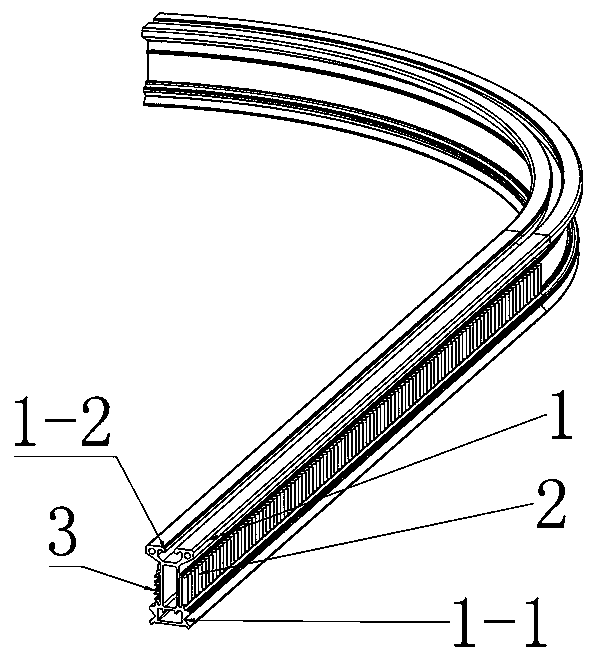
[0053] The two sides of the lower part of the V-shaped groove track 1 are respectively provided with V-shaped guide positioning grooves 1-1, and the top of the V-shaped groove track is provided with T-shaped grooves 1-2 for lifting and fixing. The two sides of the V-groove track 1 are respectively equipped with a sliding contact line 3 and a synchronous toothed belt 2.
[0054] The two sides of the V-groove track 1 are respectively equipped with a sliding contact line 3 and a synchronous toothed belt 2. According to the location of the electrical equipment or electrical cabinet, the V-groove track 1 is fixedly arranged along the installation position of the electrical equipment or electrical cabinet. The V-groove track 1 is arranged in a revolving and turning shape, which is conve...
PUM
Abstract
The invention relates to the field of intelligent detection robots, in particular to a rail suspension intelligent inspection robot system. The rail suspension intelligent inspection robot system comprises a V groove rail, a walking trolley, a lifting mechanism and a camera shooting rotating pan tilt; a trolley conductor and a synchronous tooth belt are arranged on the two sides of the V groove rail correspondingly, the walking trolley comprises a rotating hanging frame, a walking synchronous wheel, a swing sliding table, an ejector rod reset mechanism, a walking trolley stepping servo motor,a walking trolley upper base plate, a walking trolley lower base plate and a connecting rod, the lifting mechanism is composed of a lifting mechanism stepping servo motor, a first worm, a worm supporting frame, a first worm gear, a screw transmission shaft, a multi-stage screw, a screw nut, a fixed guide rod, and a guide telescopic rod, the camera shooting rotating pan tilt is composed of a pan tilt body, a camera rotating mechanism, and a pan tilt rotating mechanism, and the camera rotating mechanism comprises a camera rotating shaft, a rotating shaft bearing base, a third worm gear, a thirdworm, a worm supporting frame and a camera rotating stepping servo motor.
Description
Technical field [0001] The invention relates to the field of intelligent inspection robots, in particular to a rail suspension intelligent inspection robot system. Background technique [0002] At present, in some important equipment rooms or power distribution stations, manual watch is arranged and the operation status of the equipment is regularly inspected. In such day-to-day repetitive work, it is easy to form a kind of inspection fatigue, which makes people feel The state of numbness caused omissions in the early signals and signs of instability of some equipment during inspections. When equipment failure occurs, it will often cause major property losses, and even major accidents of personal injury. Therefore, people think of using robots to replace manual duty to improve the problems in manual duty. However, the existing inspection robots on the market still have some shortcomings. For example, the walking mechanism of some inspection robots is driven by friction wheels. I...
Claims
Application Information
Patent Timeline
Application Date:The date an application was filed.
Publication Date:The date a patent or application was officially published.
First Publication Date:The earliest publication date of a patent with the same application number.
Issue Date:Publication date of the patent grant document.
PCT Entry Date:The Entry date of PCT National Phase.
Estimated Expiry Date:The statutory expiry date of a patent right according to the Patent Law, and it is the longest term of protection that the patent right can achieve without the termination of the patent right due to other reasons(Term extension factor has been taken into account ).
Invalid Date:Actual expiry date is based on effective date or publication date of legal transaction data of invalid patent.