Paint-free door film laminating machine

A technology of a laminating machine and a paint-free door, which is applied to wood processing appliances, manufacturing tools, etc., can solve the problems of insufficient quality of lamination of lamination films, inability to cover the outer edge of the film, and insufficient cooling effect. Achieving the effect of high arrival rate, good cooling effect and quality improvement

Inactive Publication Date: 2019-06-07
江山市标龙装饰材料有限公司
3 Cites 4 Cited by

AI-Extracted Technical Summary

Problems solved by technology

[0004] The object of the present invention is to provide a paint-free door laminating machine to solve the problem that the quality of the lamination between the covering film and the door panel at normal temperature is not high enoug...

Method used

As shown in accompanying drawing 4 to accompanying drawing 5, wherein, one side of cooling roller table 701 goes to the other side, and the inner diameter of spoiler 702 reduces slowly thereupon, and the other side of water hole 703 It runs through the spoiler 702 and extends to the interlayer 704. When the cooling roller table 701 rotates, the water flow inside the cooling roller table 701 will move along the spoiler 702 from one side to the other side as soon as possible along with the centrifugal force. At the same time, the water flow will enter the interlayer 704 from the water hole 703 on the surface of the spoiler 702, thereby making the cooling effect of the device better.
As shown in accompanying drawing 6, cutting knife 8 and cooling roller table 701 are in the same horizontal plane, and cutting knife 8 can be regulated by bolt with respect to truss 3, and cutting knife 8 can be carried out on the covering film limit on door panel side edge. cutting, thereby making the device more convenient to use.
As shown in accompanying drawing 7, hydraulic rod 102 quantity is several, is positioned at slide bar 103 tops, is symmetrically distributed on the left and right sides of fixed bottom plate 1 inner side, and hydraulic rod 102 stretches out, and door panel can be clamped and fixed, prevents The door panel is out of the way.
In the present invention, at first guarantee the completeness of device function, then, door panel is sent into the top of slide bar 103, and hydraulic rod 102 stretches out, and door panel can be clamped and fixed, prevents door panel from running off, so that cover film passes through The heating plate 501 is attached to the door panel again, and then the lead screw mover...

Abstract

The invention provides a paint-free door film laminating machine. The paint-free door film laminating machine comprises a fixed bottom plate and lead screws, the lead screws are arranged on the left and right sides of the interior of the fixed bottom plate in a penetrating mode, a lead screw mover is arranged at the upper portion of each lead screw in an inlaid mode, a sliding rod is rotatably connected with the bottom of the fixed bottom plate, hydraulic rods are fixedly connected with the left and right sides of the inner side of the front face of the fixed bottom plate, a truss is fixedly connected with the upper portions of the lead screw movers, and a film roll, a heating roller, a pressure supporting roller, and a circulating pump machine are fixedly connected with the bottom of thetruss from left to right in sequence. The paint-free door film laminating machine uses a cooling roller duct to cool the coated film by being capable of using the low temperature of the cooling rollerduct, the principle of hot expansion and cooling is used so that the coated film is fitted with a door plate more closely, and the laminating quality is improved accordingly.

Application Domain

Wood working apparatus

Technology Topic

EngineeringCirculating pump +1

Image

  • Paint-free door film laminating machine
  • Paint-free door film laminating machine
  • Paint-free door film laminating machine

Examples

  • Experimental program(1)

Example Embodiment

[0029] Example:
[0030] as attached figure 1 to attach Figure 7 Shown:
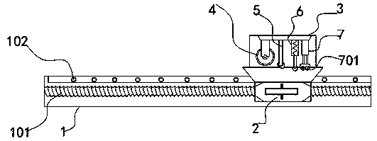
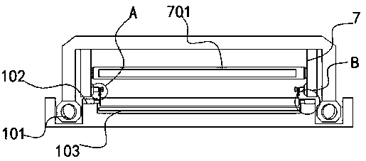
[0031] The invention provides a paint-free door laminating machine. The paint-free door laminating machine includes a fixed bottom plate 1 and a lead screw 101. The left and right sides of the fixed bottom plate 1 are provided with lead screws 101, and the two lead screws 101 are embedded The cover is provided with a lead screw mover 2, the bottom of the fixed bottom plate 1 is rotatably connected with a slide bar 103, and the left and right sides of the front inner side of the fixed bottom plate 1 are fixedly connected with hydraulic rods 102;
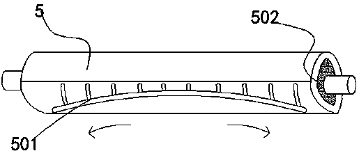
[0032] A truss 3 is fixedly connected to the top of the lead screw mover 2, and the bottom of the truss 3 is fixedly connected with a film material roll 4, a heating roller 5, an auxiliary pressure roller 6, and a circulation pump 7 in order from left to right. The surface of the heating roller 5 is integrated with The heating plate 501 is fixedly connected with the heating wire 502 inside the heating roller 5, and the cooling roller table 701 is rotatably connected to the bottom of the circulation pump 7 through the connecting piece, and the interlayer 704 is embedded in the cooling roller table 701, and the inner surface of the interlayer 704 is integrated. There is a spoiler 702, the surface of the spoiler 702 is penetrated with a water hole 703, and the inner side of the truss 3 is movably connected with a cutting knife 8.
[0033] as attached image 3 As shown, among them, the heating plate 501 is a copper heating plate 501, which is arc-shaped, protruding outward, and has a smooth surface, and at the same time, the upper surface is embedded with outwardly protruding stripes, so that the heating wire 502 generates heat. The warming plate 501 and the striped pattern above can heat the covering film passing through the lower surface of the heating roller 5, and at the same time make it extend to both sides, which is more convenient for bonding with the paint-free door.
[0034] as attached Figure 4 to attach Figure 5 As shown, wherein, from one side of the cooling roller table 701 to the other side, the inner diameter of the spoiler 702 gradually decreases, and the other side of the water hole 703 runs through the spoiler 702 and extends to the interlayer 704 When the cooling roller table 701 rotates, the water flow inside the cooling roller table 701 will move along the spoiler 702 from one side to the other side as soon as possible along with the centrifugal force, and at the same time, the water flow will pass through the surface of the spoiler 702 The water hole 703 enters into the interlayer 704, thereby making the cooling effect of the device better.
[0035] as attached Image 6 As shown, the cutting knife 8 and the cooling roller table 701 are in the same horizontal plane, and the cutting knife 8 can be adjusted by bolts relative to the truss 3, and the cutting knife 8 will cut the covering film edge on the side edge of the door panel, so that the device is running It is more convenient to use.
[0036] as attached Figure 7 As shown, there are several hydraulic rods 102, located above the slide rod 103, symmetrically distributed on the left and right sides of the inner side of the fixed bottom plate 1, and the hydraulic rods 102 protrude to clamp and fix the door panel to prevent the door panel from running off.
[0037] Wherein, the auxiliary pressure roller 6 and the cooling roller table 701 can be stretched, and the shaft ends of the film material roll 4, the auxiliary pressure roller 6, and the cooling roller table 701 are all connected by chains and move synchronously. The cover film is pressed on the surface of the door panel, and the cooling roller table 701 can use its low temperature to cool the cover film, and use the principle of thermal expansion and contraction to make the cover film and the door panel more tightly bonded and improve the quality of the cover film.
[0038] Wherein, both sides of the cooling roller table 701 are connected to the circulation pump 7 through pipelines, and the circulation pump 7 can keep the water flow inside the cooling roller table 701 at low temperature, improving the cooling quality of the covering film.
[0039] The specific usage and function of this embodiment:
[0040]In the present invention, firstly, the integrity of the device function is ensured, and then, the door panel is sent above the slide rod 103, and the hydraulic rod 102 is stretched out, which can clamp and fix the door panel to prevent the door panel from running off, so that the covering film passes through the heating plate 501 is attached to the door panel again, and then the lead screw mover 2 drives the truss 3 to move, and at the same time, the heating wire 502 is heated, and the heating plate 501 and the strip pattern above can be used to cover the lower surface of the heating roller 5 The film is heated, and at the same time, the arc-shaped heating plate 501 makes the covering film extend to both sides, which is more convenient for lamination with the paint-free door, and the film material roll 4, auxiliary pressure roller 6, cooling roller table 701 shaft end They are all connected by chains and move synchronously. The auxiliary pressure roller 6 can press the heated cover film on the surface of the door panel, and the circulation pump 7 can keep the water flow inside the cooling roller table 701 at low temperature. At this time, the water flow inside the cooling roller table 701 will move along the spoiler 702 from one side to the other side as soon as possible along with the centrifugal force, and at the same time, the water flow will enter the interlayer 704 from the water hole 703 on the surface of the spoiler 702, The cooling roller table 701 can use its low temperature to cool down the cover film, and use the principle of thermal expansion and contraction to make the cover film and the door panel more tightly bonded and improve the quality of the cover film. Finally, the cutting knife 8 will meet the side edge of the door panel. The edge of the cover film on the top is cut, which makes the device more convenient to use.

PUM

no PUM

Description & Claims & Application Information

We can also present the details of the Description, Claims and Application information to help users get a comprehensive understanding of the technical details of the patent, such as background art, summary of invention, brief description of drawings, description of embodiments, and other original content. On the other hand, users can also determine the specific scope of protection of the technology through the list of claims; as well as understand the changes in the life cycle of the technology with the presentation of the patent timeline. Login to view more.

Similar technology patents

Method for improving quality of strong aromatic dry distilled grain

ActiveCN101705167AIncrease the acidity in the cellarquality improvement
Owner:SICHUAN TUOPAI SHEDE WINE

Jujube tree grafting method

InactiveCN103070025Aprevent dehydrationquality improvement
Owner:XINJIANG ACADEMY OF AGRI & RECLAMATION SCI

High-yield pollution-free breeding method of freshwater fish

Owner:靖江市华信科技创业园有限公司

Friction-stir welding equipment

ActiveCN104985320Aquality improvementReduce torsional or impact forces
Owner:重庆派馨特机电有限公司

Classification and recommendation of technical efficacy words

  • good cooling effect
  • quality improvement

Rice machining process

InactiveCN103691508Aquality improvementReduce broken rice rate
Owner:聂俊
Why Eureka
Try Eureka