Lateral drive shaft of drive train of motor vehicle comprising internal combustion engine and transducer

A powertrain, lateral drive technology used in vehicle components, transport and packaging, controls, etc. to address issues such as comfort impacts

Pending Publication Date: 2019-06-07
FORD GLOBAL TECH LLC
View PDF1 Cites 0 Cited by
  • Summary
  • Abstract
  • Description
  • Claims
  • Application Information

AI Technical Summary

Problems solved by technology

As a result, comfort is affected in a particularly unfavorable way

Method used


Image

  • Lateral drive shaft of drive train of motor vehicle comprising internal combustion engine and transducer
  • Lateral drive shaft of drive train of motor vehicle comprising internal combustion engine and transducer

Examples


Embodiment Construction

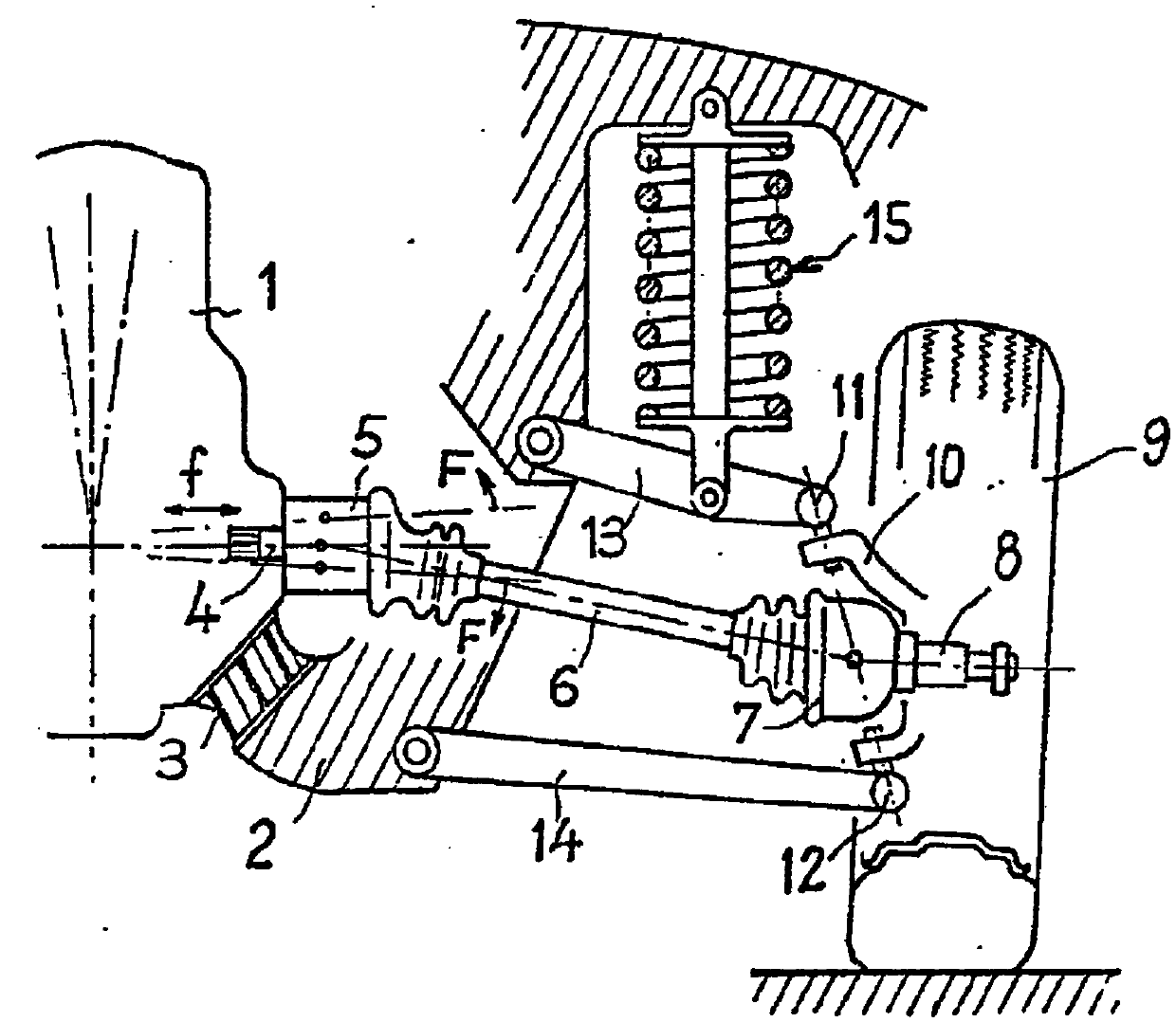
[0060] has been described in conjunction with discussions of the prior art figure 1 , so reference is made at this point to the corresponding expression.

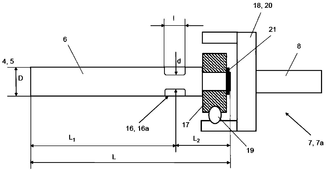
[0061] figure 2 A first embodiment of a transverse drive shaft 6 of a drive train together with an outboard constant velocity joint 7 and a shaft head 8 is schematically shown. only to indicate that relative to figure 1 Additional features of , therefore, additionally refer to figure 1 and related descriptions. The same reference names have been used for the same parts.

[0062] In the installed position, the transverse drive shaft 6 is connected to the transmission output shaft 4 of the drive unit via the inboard constant velocity joint 5 and can be set in rotation via the transmission output shaft 4 .

[0063] The drive shaft 6 is connected via an outboard constant velocity joint 7 to a steerable wheel, which is received by an axle head 8 .

[0064] In the present case, the outer constant velocity joint 7 is a cage...


PUM


Abstract

The invention relates to a lateral drive shaft (6) of a drive train which can be connected via an internal constant velocity joint (5) to a transmission output shaft (4) of a drive unit (1) and via anexternal constant velocity joint (7) to a steerable wheel (9). It should be provided a lateral drive shaft (6) of the type mentioned, with which in the suspension or Wheel bearing and the body (2) introduced radial vibrations or the forces causing these vibrations at least reduced, if necessary, be eliminated. This object is achieved by a lateral drive shaft (6), which is characterized in that the lateral drive shaft (6) has at least one notch (16).

Description

technical field [0001] The present invention relates to a transverse drive shaft of a powertrain, which is connectable via an inboard constant velocity joint to a transmission output shaft of a drive unit and via an outboard constant velocity joint to steerable wheels. Background technique [0002] Development work in the field of vehicle acoustics has focused from the outset on noise reduction. The most obvious in this regard is firstly the internal combustion engine as the main noise source of the motor vehicle and then also the auxiliary units which are decisive for the overall noise emission. [0003] Attempts are increasingly being made not only to reduce the noises caused by motor vehicles, but also to influence or use them in a targeted manner, which is often also referred to as noise design or sound design. This development work was facilitated by the realization that the purchasing decisions of potential customers when purchasing a vehicle are not negligibly influe...

Claims


Application Information

Patent Timeline
Patent Type & Authority Applications(China)
IPC IPC(8): B60K17/22
CPCB60K17/22
Inventor 迈克尔·勒里希雷纳·格兰霍斯特丹尼尔·基尔斯皮尔奥莱·雷克
Owner FORD GLOBAL TECH LLC
Why Eureka
Try Eureka