Sinker device for flat knitting machine head, flat knitting machine head and flat knitting machine

A technology of flat knitting knitting machine and machine head, which is applied in the directions of knitting, weft knitting, textile and paper making, etc., can solve the problems of incomplete knitting, damaged knitted fabric, insufficient working width of sinkers, etc., so as to improve the knitting effect, The effect of improving stability

Active Publication Date: 2019-06-07
ZHEJIANG FENGFAN NC MACHINERY
View PDF10 Cites 1 Cited by
  • Summary
  • Abstract
  • Description
  • Claims
  • Application Information

AI Technical Summary

Problems solved by technology

The existing sinker control mechanism is generally divided into two structures: up and down and left and right. The disadvantage of the existing up and down sinker control mechanism is that the working width of the sinker is insufficient when the sinker is pressed. It has been released before reaching the maximum withdrawal height. When performing partial knitting, it is easy to cause the situation that the knitting cannot be completely withdrawn, which will cause damage to the knitted fabric
Although the existing left and right row sinker control mechanism can make the sinker have sufficient working width, but the depth of pushing the sinker to press is fixed, and the connection structure between the sinker control mechanism and the sinker needs to be manually disassembled to adjust the sinker It is difficult to ensure the consistency of the sinker's pressing depth
When the pressing depth of the sinker satisfies the local knitting requirements, it is easy to crush the coils during the relatively tight coil transfer, which will cause damage to the braided fabric
Therefore, the existing sinker control mechanism cannot combine the advantages of both up and down and left and right structures, that is, it is impossible to ensure that the sinker has a large working width and at the same time ensure that the sinker has an adjustable pressing depth

Method used


Image

  • Sinker device for flat knitting machine head, flat knitting machine head and flat knitting machine
  • Sinker device for flat knitting machine head, flat knitting machine head and flat knitting machine
  • Sinker device for flat knitting machine head, flat knitting machine head and flat knitting machine

Examples


Embodiment 1

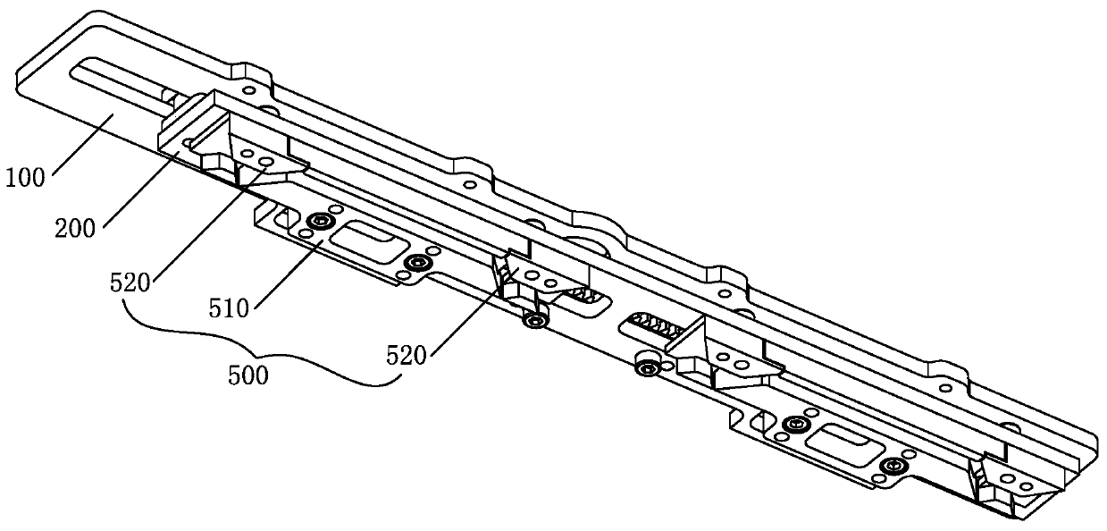
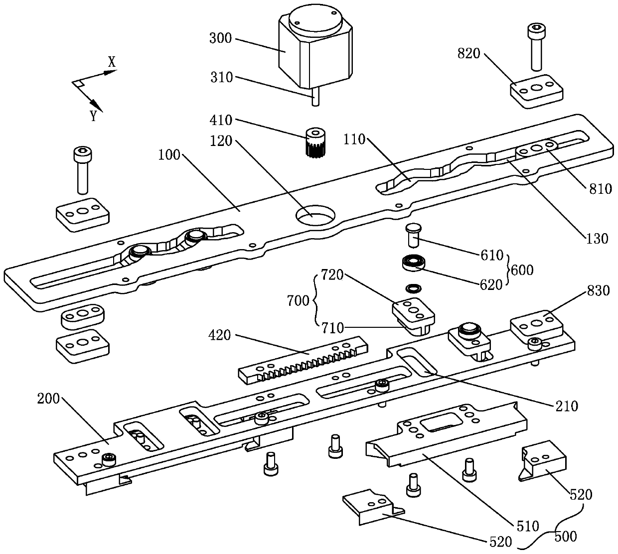
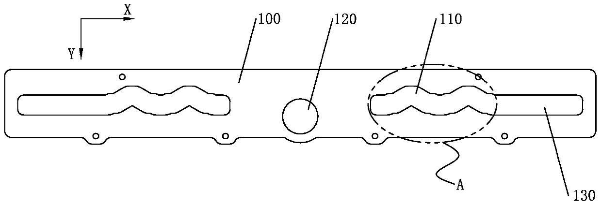
[0032] Such as figure 1 , figure 2 , image 3As shown, the Sink device of the flat knitting machine head provided by Embodiment 1 of the present invention includes a bottom plate 100, a slide bar 200, a motor 300, a transmission structure and at least one set of Sink triangle groups 500, and the slide bar 200 is arranged on the bottom plate 100 and can move back and forth laterally relative to the bottom plate 100. The Singer triangle group 500 is arranged on the bottom surface of the slide bar 200, and each group of Singer triangle group 500 includes a pusher triangle 510 and a return triangle 520, and the return triangle 520 is provided with two One and two restoring triangles 520 are symmetrically arranged at both lateral ends of the pushing triangle 510, and the transmission structure is arranged between the motor 300 and the slide bar 200. When the motor 300 works, the drive structure drives the slide bar 200 to move back and forth in the lateral direction to realize th...


PUM


Abstract

The invention discloses a sinker device for a flat knitting machine head, the flat knitting machine head and a flat knitting machine, and belongs to the field of flat knitting machines. The sinker device comprises a bottom plate, a sliding bar, a motor, a transmission structure and sinker cam sets, wherein the sliding bar is arranged on the bottom of the bottom plate and can move forth and back inthe transverse direction, the sinker cam sets are arranged on the bottom face of the sliding bar, and each sinker cam set comprises a pushing cam and restoration cams. When the motor works, the sliding bar is driven by the transmission structure to move forth and back in the transverse direction to achieve transverse movement of the sinker cam sets, and the pushing cams are movably connected to the sliding bar. A driving groove is formed in the bottom plate, the driving groove is partly inclined relative to the transverse direction, a driving piece connected to the pushing cams is arranged inthe driving groove, and during translation of the sliding bar, the driving piece drives the pushing cams to move in the direction inclined relative to the transverse direction by cooperating with thedriving groove, so that longitudinal movement of the sinker cam sets is achieved. While a sinker has a high work width, it is ensured that the pressing depth of the sinker can be adjusted, and the knitting effect can be improved.

Description

technical field [0001] The present invention relates to the technical field of flat knitting machines, in particular to a gramming device of a flat knitting machine head. In addition, the present invention also relates to a gramming device of a flat knitting machine using such a gramming device. Head of flat knitting machine. Background technique [0002] The working principle of the existing flat knitting machine is generally to make the yarn complete the actions of lapping, closing, looping, bending, stripping and looping through the regular lifting movement of the knitting needles to weave the yarn into a braided fabric. During the rising process of the knitting needle, the coil gradually withdraws from the needle hook and opens the needle latch, which hangs on the needle bar. When the knitting needle is lowered, the needle hook catches the yarn of the new pad and pulls it to form a new loop. At the same time, the original loop breaks away from the needle hook, and the n...

Claims


Application Information

Patent Timeline
Patent Type & Authority Applications(China)
IPC IPC(8): D04B15/36D04B15/96
CPCY02P70/62
Inventor 付洪平陈德伟卓可煌华晓燕
Owner ZHEJIANG FENGFAN NC MACHINERY
Why Eureka
Try Eureka