AI technical title is built by Patsnap AI team. It summarizes the technical point description of the patent document.
An automatic laying and multi-functional technology, applied in the field of construction equipment, can solve the problems of high work intensity, low work efficiency, and large workload of workers, and achieve the effect of reducing work intensity and improving work efficiency.
Active Publication Date: 2019-06-07
岳西县双节路桥工程有限公司
View PDF7 Cites 11 Cited by
Summary
Abstract
Description
Claims
Application Information
AI Technical Summary
This helps you quickly interpret patents by identifying the three key elements:
Problems solved by technology
Method used
Benefits of technology
Problems solved by technology
[0002] In building construction, most floor tiles are now laid by hand, whether it is home decoration, laying floor tiles, or paving sidewalks on both sides of the road, and the sidewalks are long and wide, and laying is time-consuming and laborious. After laying floor tiles, it is necessary Beating and reinforcing the floor tiles requires high work intensity, heavy workload and low work efficiency, so a multifunctional floor tile automatic laying device is designed to solve this problem
Method used
Image
Click on the blue label to locate the original text in one second.
Reading with bidirectional positioning of images and text.
Examples
specific Embodiment approach 1
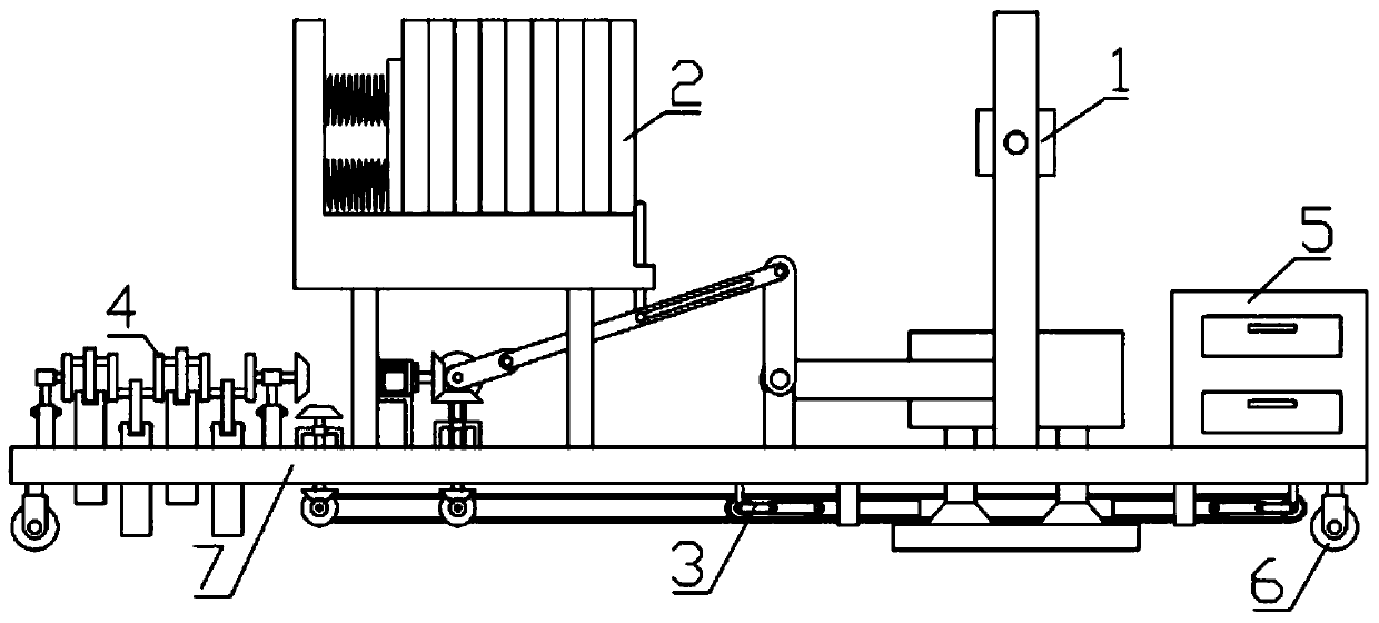
[0031] Combine below figure 1 , figure 2 , image 3 , Figure 4 , Figure 5 , Image 6 , Figure 7 , Figure 8 , Figure 9 , Figure 10 , Figure 11 , Figure 12 , Figure 13 , Figure 14 , Figure 15 Describe this embodiment mode, the present invention relates to a kind of construction equipment, more specifically a kind of multifunctional floor tile automatic laying device, comprising floor tile laying mechanism 1, floor tile transportation mechanism 2, brick unloading mechanism 3, floor tile laying and beating mechanism 4, storage Box 5, roller 6, base 7, the device can automatically lay the floor tiles, the device can transport the floor tiles, provide for use, the device can unload the floor tiles, complete the laying of the floor tiles, the device can beat the floor tiles, make the floor tiles lay firmly, improve the work efficiency of workers, Reduce work intensity.
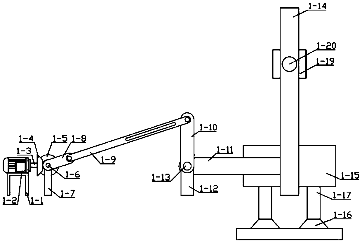
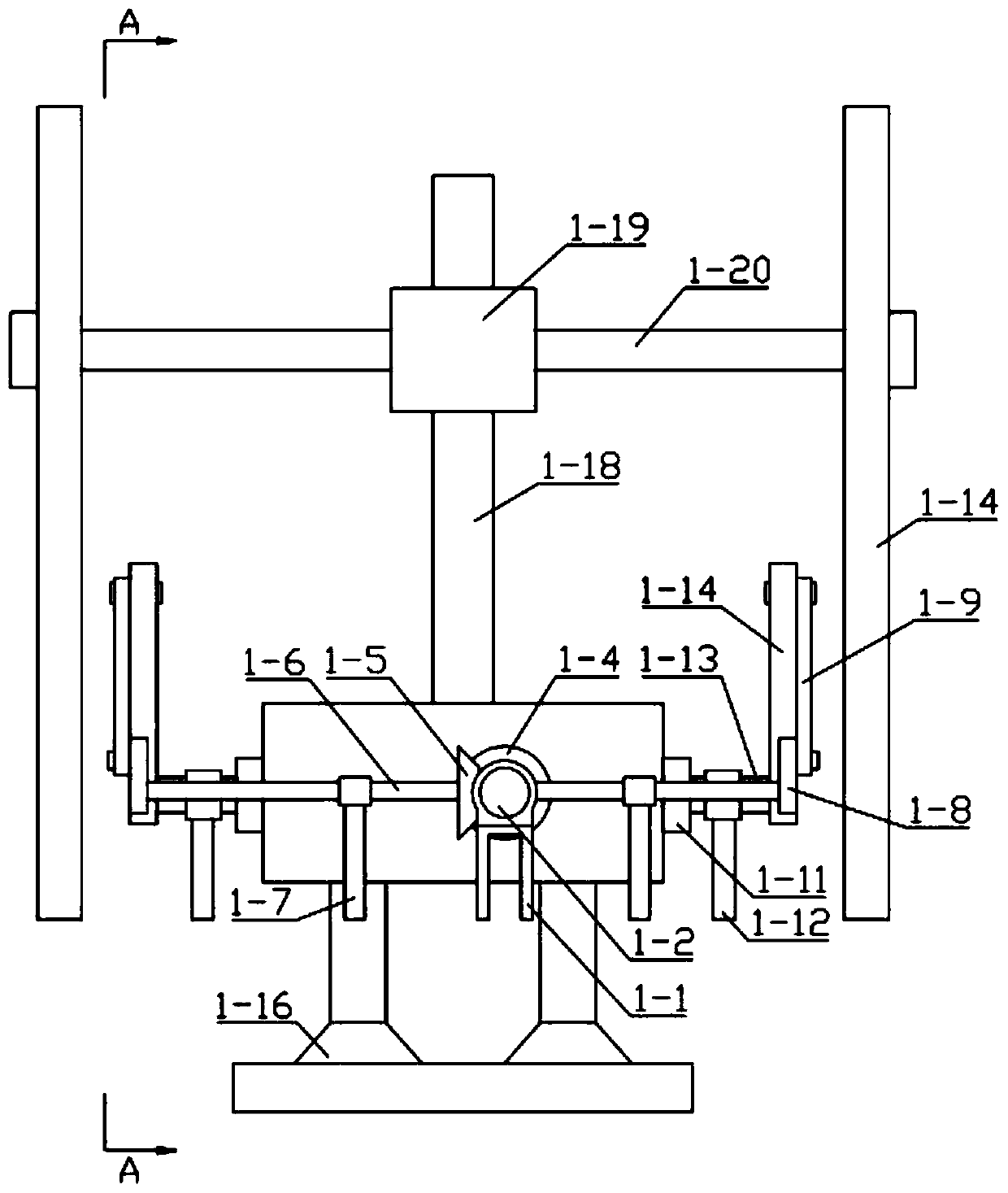
[0032] The floor tile laying mechanism 1 includes a motor fixing frame 1-1, a motor 1-2,...
specific Embodiment approach 2
[0038] Combine below figure 1 , figure 2 , image 3 , Figure 4 , Figure 5 , Image 6 , Figure 7 , Figure 8 , Figure 9 , Figure 10 , Figure 11 , Figure 12 , Figure 13 , Figure 14 , Figure 15 This embodiment will be described, and this embodiment will further describe Embodiment 1. The materials of the suction disc 1-16 and the beating glue column 4-16 are the same, both of which are rubber.
[0039] How to use the device: The device can automatically lay floor tiles, motor shaft 1-3 drives bevel gear 1-4 to rotate, bevel gear 1 1-4 drives bevel gear 2 1-5 to rotate, bevel gear 2 1-5 drives connecting shaft 1 1-6 rotates, connecting shaft one 1-6 drives curved rod one 1-8 to rotate, curved rod one 1-8 drives curved rod two 1-9, curved rod two 1-9 drives curved rod three 1-10 to rotate, and curved rod two 1-9 drives curved rod three 1-10 to rotate, Rod three 1-10 drives connecting shaft two 1-13 to rotate, connecting shaft two 1-13 drives curved rod four...
PUM
Abstract
The invention relates to construction equipment, more specifically to a multifunctional floor tile automatic laying device. The multifunctional floor tile automatic laying device comprises a floor tile laying mechanism, a floor tile transporting mechanism, a tile unloading mechanism, a floor tile laying and hammering mechanism, a storage box, rolling wheels and a base. The multifunctional floor tile automatic laying device can automatically lay floor tiles, can transport the floor tiles for use, can unload the floor tiles to finish the laying of the floor tiles, and can hammer the floor tilesso that the floor tiles are firmly laid; and therefore, the working efficiency of a worker is enhanced, and the working intensity is reduced. The left end of the base is connected with the floor tilelaying and hammering mechanism; the middle part of the base is connected with the floor tile laying mechanism; the bottom end of the base is connected with the tile unloading mechanism; the floor tilelaying mechanism is connected with the tile unloading mechanism; the tile unloading mechanism is connected with the floor tile laying and hammering mechanism; the right end of the base is connected with the storage box; and the two ends of the base are connected with the rolling wheels.
Description
technical field [0001] The invention relates to a construction device, more specifically to a multifunctional floor tile automatic laying device. Background technique [0002] In building construction, most floor tiles are now laid by hand, whether it is home decoration, laying floor tiles, or paving sidewalks on both sides of the road, and the sidewalks are long and wide, and laying is time-consuming and laborious. Floor tiles are beaten and reinforced, the work intensity is high, the workload of workers is heavy, and the work efficiency is low, so a multifunctional floor tile automatic laying device is designed to solve this problem. Contents of the invention [0003] The technical problem mainly solved by the present invention is to provide a multifunctional floor tile automatic laying device. The floor tiles are laid firmly, which improves the work efficiency of workers and reduces work intensity. [0004] In order to solve the above technical problems, the present i...
Claims
Application Information
Patent Timeline
Application Date:The date an application was filed.
Publication Date:The date a patent or application was officially published.
First Publication Date:The earliest publication date of a patent with the same application number.
Issue Date:Publication date of the patent grant document.
PCT Entry Date:The Entry date of PCT National Phase.
Estimated Expiry Date:The statutory expiry date of a patent right according to the Patent Law, and it is the longest term of protection that the patent right can achieve without the termination of the patent right due to other reasons(Term extension factor has been taken into account ).
Invalid Date:Actual expiry date is based on effective date or publication date of legal transaction data of invalid patent.

