Double fan-shaped gear beam extended range pumping unit

A sector gear and pumping unit technology, applied in wellbore/well components, production fluids, earth-moving drilling, etc., can solve the problems of low chain service life, low belt winding life, large reversing impact force, etc., and achieve reliable performance. The effect of good performance, less floor space and smooth movement

Active Publication Date: 2019-06-07
大庆诺源石油科技发展有限公司
View PDF16 Cites 2 Cited by
  • Summary
  • Abstract
  • Description
  • Claims
  • Application Information

AI Technical Summary

Problems solved by technology

[0004] Although the above-mentioned prior art has its own characteristics, it has also realized the range extension of the pumping unit to a certain extent, but there are still some technical problems: for example, the reliability of the electric commutation in the patent CN1061739C is not good enough; in the patent CN100564794C The mechanical reversing device of the lever-balanced sky-wheel long-stroke pumping unit has a large reversing impact force. At the same time, there are too many wheels in the speed-changing structure of the sky wheel, and they are arranged on the top of the frame. The belt winding life is low and the structure is relatively complicated; patent CN1007997B The chain-type range-extending mechanism is adopted, and the service life of the chain is low, etc.

Method used


Image

  • Double fan-shaped gear beam extended range pumping unit
  • Double fan-shaped gear beam extended range pumping unit
  • Double fan-shaped gear beam extended range pumping unit

Examples


Embodiment 1

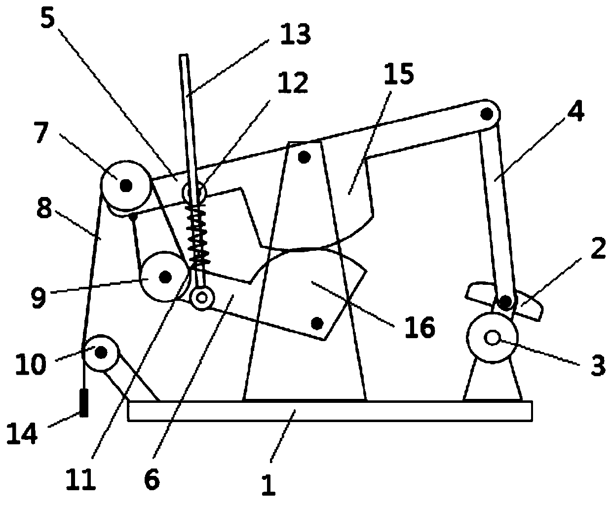
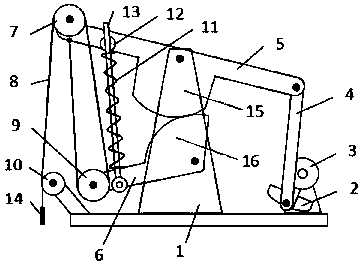
[0025] Such as Figure 1~2 As shown, this embodiment provides a double-sector gear beam extended-range oil pumping unit, including a base 1, a motor reducer, a crank 3, a connecting rod 4, an upper beam 5, a lower beam 6, an upper pulley 7, a steel wire belt 8, The lower pulley 9, the guide roller 10, the spring 11, the guide rod 13, the straight pin 12 and the sucker rod 14, the upper beam 5 is provided with the first sector gear 15 and the first gear center through hole, and the lower beam 6 is provided with The second sector gear 16 and the center through hole of the second gear, the first gear center through hole is rotationally connected with the upper middle of the base 1 through a pin shaft, the first sector gear 15 rotates around the axis where the first gear center through hole is located, The center through hole of the second gear rotates and connects with the middle bottom of the base 1 through the pin shaft, and the second sector gear 16 rotates around the axis where...


PUM


Abstract

The invention discloses a double fan-shaped gear beam extended range pumping unit. The double fan-shaped gear beam extended range pumping unit comprises a engine base, a motor reducer, a crank, a connecting rod, an upper beam, a lower beam, an upper belt pulley, a lower belt pulley, a steel wire belt, a guide roller, a spring, a guide rod, cylinder pins and a sucker rod; a driving shaft of the motor reducer is connected with a crank key, the crank is rotatably connected with the connecting rod, the upper beam is rotatably connected with the engine base, the upper belt pulley and the connectingrod, the lower beam is rotatably connected with the engine base and the lower belt pulley, and a gear of the upper beam meshes with a gear of the lower beam; one end of the steel wire belt is connected with the sucker rod, and the other end is connected with the upper beam after passing through the guide roller, the upper belt pulley and the lower belt pulley; and the spring sleeves the guide rod, and the two ends abut against the upper beam and the lower beam. The motor reducer drives the upper beam and the lower beam to swing in the reverse direction through the crank and the connecting rod, and the reciprocating vertical extended range motion of the sucker rod is realized through the upper belt pulley, the lower belt pulley and the steel belt, the stroke of the sucker rod is long, andthe reversing is continuous without impact during the upstroke and the down stroke, the balance weight of the lower belt pulley and the crank and the spring can assist a motor in lifting oil pumping and prevent the sucker rod self-weight from driving the motor to carry out generate electricity, and the operation is reliable.

Description

technical field [0001] The invention relates to the technical field of oil exploitation equipment, in particular to a double-sector gear beam extended-range pumping unit. Background technique [0002] In shallow and deep well oil production conditions, rod-type beam pumping units have been widely used in late-stage oil production in oil fields all over the world because of their continuous and non-impacting sucker rod reversing process, simple structure, and reliability. In deep well oil production conditions, due to the large elastic elongation of the sucker rod, it is often necessary to increase the stroke of the sucker rod in order to effectively improve the pumping efficiency of the pumping unit and reduce energy consumption; The stroke of the sucker rod of the oil engine will cause the length and total weight of the beam to double, which will double the manufacturing cost, driving torque and floor space, and make its safety worse. Therefore, experts in the field of oil...

Claims


Application Information

Patent Timeline
Patent Type & Authority Applications(China)
IPC IPC(8): E21B43/00
Inventor 路懿路扬常泽锋叶妮佳
Owner 大庆诺源石油科技发展有限公司
Why Eureka
Try Eureka