Gear train self-lubricating device

A self-lubricating, gear train technology, applied in the direction of gear lubrication/cooling, etc., can solve the problems of occupying a large space and cannot be applied to a work site with a small space, etc., achieving the effect of simple structure, reduced equipment volume, and wide application range.

Active Publication Date: 2019-06-07
山西煤矿机械制造股份有限公司
View PDF8 Cites 0 Cited by
  • Summary
  • Abstract
  • Description
  • Claims
  • Application Information

AI Technical Summary

Problems solved by technology

[0004] The inventors have found that the prior art has at least the following problems: forced lubrication through an external lubrication pump system takes up a lot of space and cannot be applied to working sites with small spaces

Method used


Image

  • Gear train self-lubricating device
  • Gear train self-lubricating device
  • Gear train self-lubricating device

Examples


Embodiment Construction

[0026] In order to make the purpose, technical solution and advantages of the present invention clearer, the technical solution of the present invention will be clearly and completely described below in conjunction with specific embodiments of the present invention and corresponding drawings. Apparently, the described embodiments are only some of the embodiments of the present invention, but not all of them. Based on the embodiments of the present invention, all other embodiments obtained by persons of ordinary skill in the art without making creative efforts fall within the protection scope of the present invention.

[0027] The technical solutions provided by the embodiments of the present invention will be described in detail below in conjunction with the accompanying drawings.

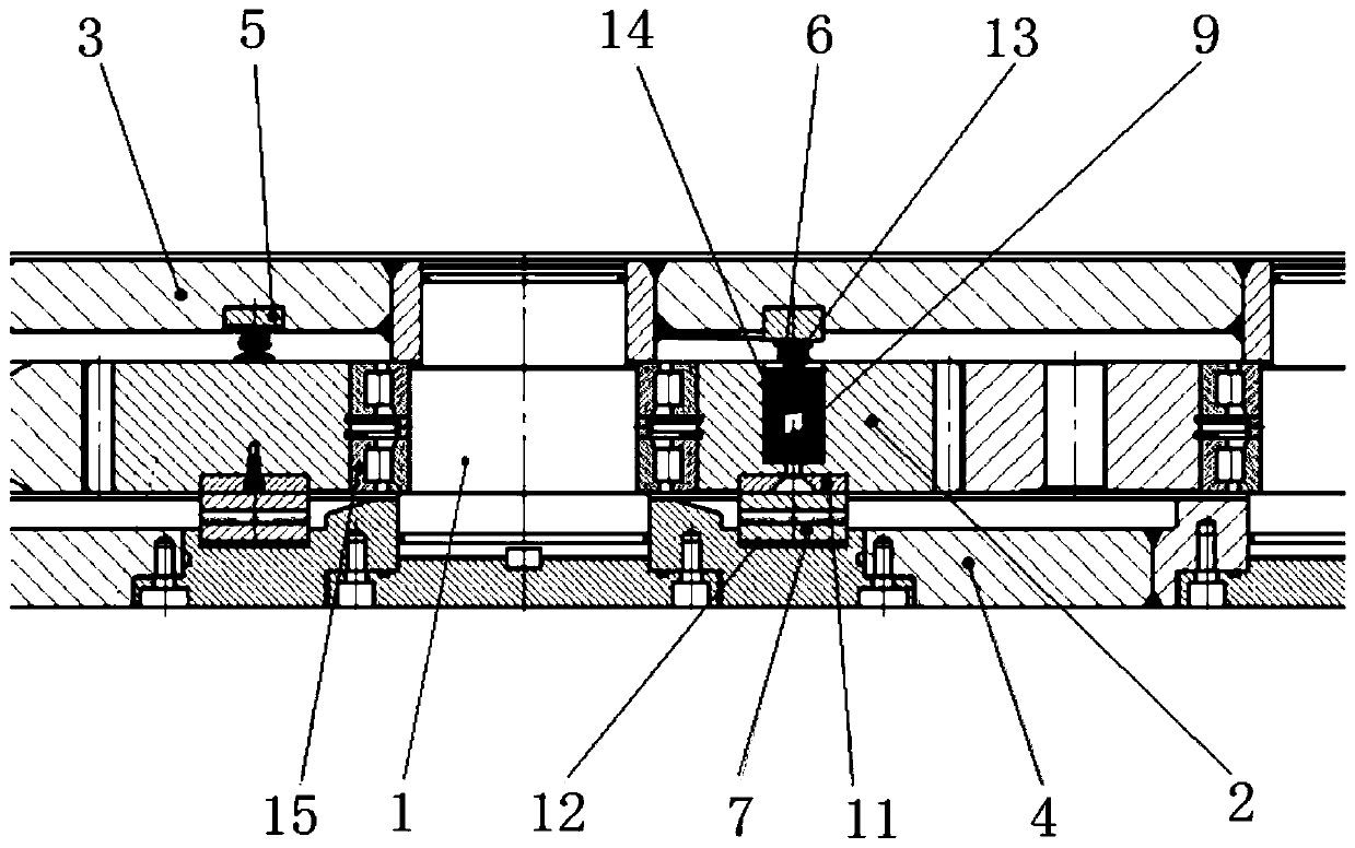
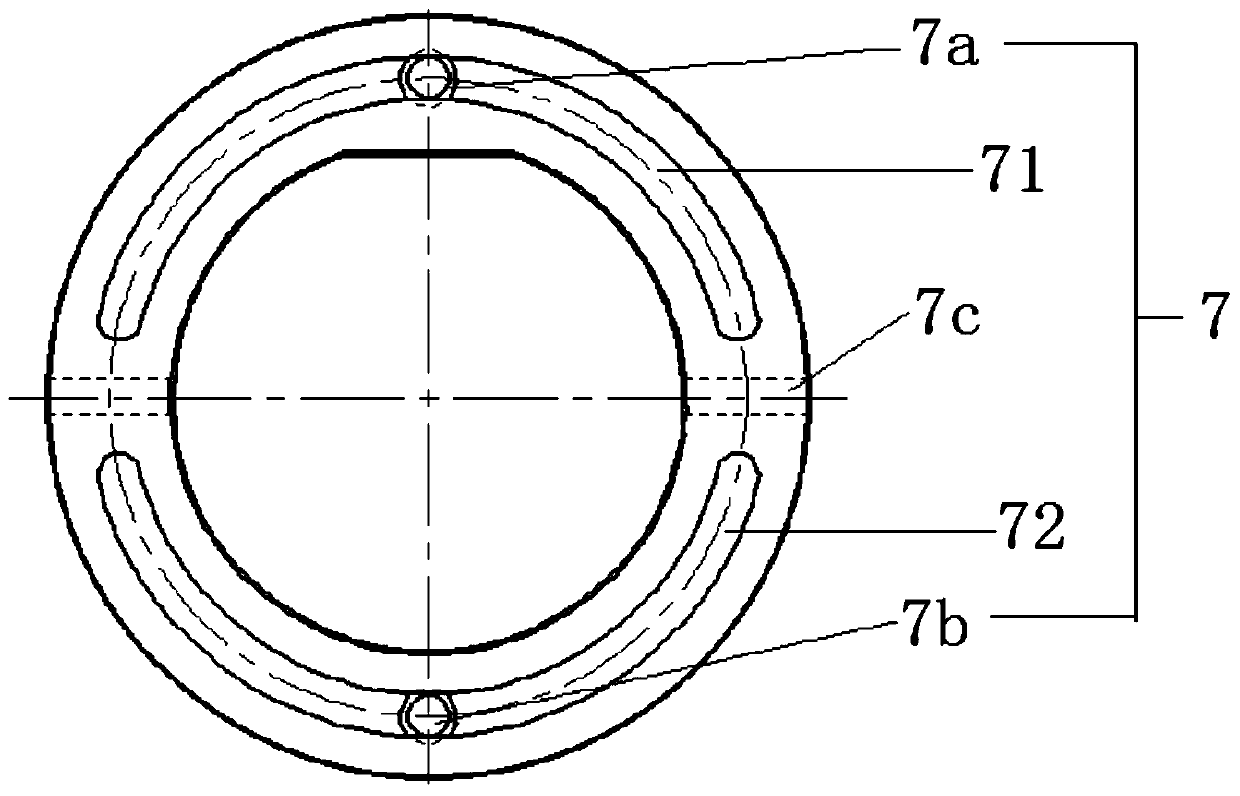
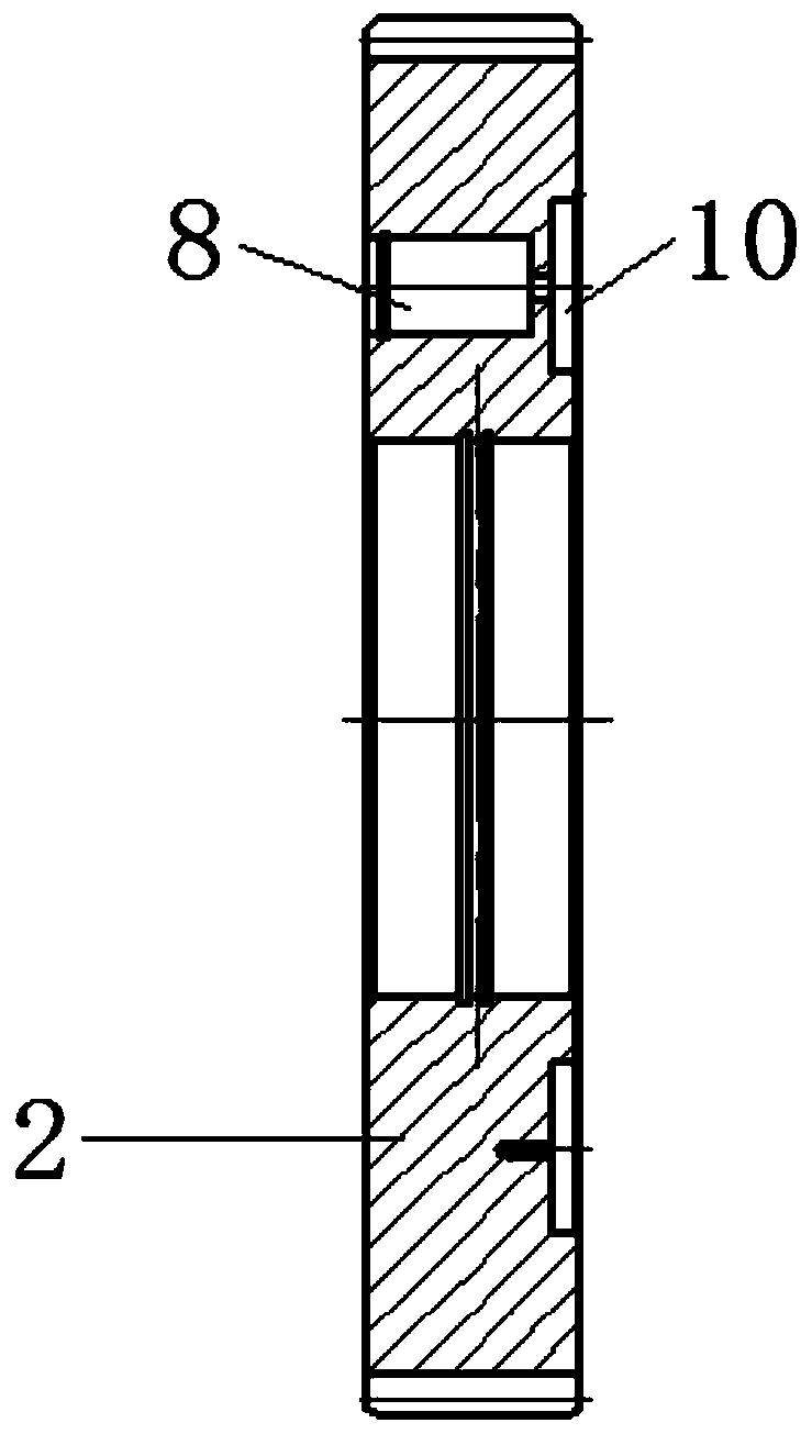
[0028] The embodiment of the present invention provides a gear train self-lubricating device, such as the attached Figures 1 to 5 As shown, the device includes: a gear shaft 1, a gear 2, a first ...


PUM


Abstract

The invention discloses a gear train self-lubricating device. The gear train self-lubricating device comprises a gear shaft, a gear, a first shell, a second shell, a swash plate, a plunger and an oildistribution disk. The gear shaft is rotatably sleeved with the gear. The first shell and the second shell are arranged on the two sides of the gear correspondingly. The swash plate is arranged on theinner wall of the first shell. The thickness of the swash plate gradually changes in the circumferential direction. The gear is provided with a plunger hole in the axial direction. The plunger is located in the plunger hole and supported through an elastic part. When the gear rotates, the top end of the plunger abuts against the swash plate. The oil distribution disk is arranged on the inner wallof the second shell, communicates with the bottom end of the plunger hole and is used for filling oil into the plunger hole or discharging lubricating oil in the plunger hole. According to the gear train self-lubricating device provided by the invention, the lubricating oil is transferred from one side of the oil distribution disk to the other side of the oil distribution disk along with rotationof the gear to achieve the lubricating effect. There is no need to additionally pump in pressure. The gear train self-lubricating device is simple in structure and wide in application range, and thesize of equipment is reduced.

Description

technical field [0001] The invention relates to the technical field of mechanical transmission, in particular to a gear train self-lubricating device. Background technique [0002] In industrial transmission systems, gear transmission accounts for a large proportion and is one of the main transmission forms at present, such as gearboxes and synchronous gears in transportation equipment. In gear transmission equipment, in order to make good contact between the various components and prolong the service life, the transmission gear needs to be lubricated. [0003] Lubrication is carried out in the following manner in the prior art: lubricating oil is input into the gearbox through an external lubricating pump system and a gear pump for forced lubrication. [0004] The inventors have found that the prior art has at least the following problems: forced lubrication through an external lubricating pump system takes up a lot of space and cannot be applied to a working site with a s...

Claims


Application Information

Patent Timeline
Patent Type & Authority Applications(China)
IPC IPC(8): F16H57/04
Inventor 樊建军谢地文卫星高丽霞王宏宇逯盛华
Owner 山西煤矿机械制造股份有限公司
Why Eureka
Try Eureka