[0046] Hereinafter, the present invention will be further described based on preferred embodiments and with reference to the drawings.
[0047] In addition, in order to facilitate understanding, various components on the drawing are enlarged (thick) or reduced (thin), but this approach is not intended to limit the protection scope of the present invention.
[0048] Words in the singular form also include plural meanings and vice versa.
[0049] The vocabulary in this specification is used to illustrate the embodiments of the present invention, but is not intended to limit the present invention.
[0050] In order to distinguish different units, terms such as first and second are used in this specification, but these are not restricted by the order of manufacture, and their names may be different in the detailed specification and claims of the invention.
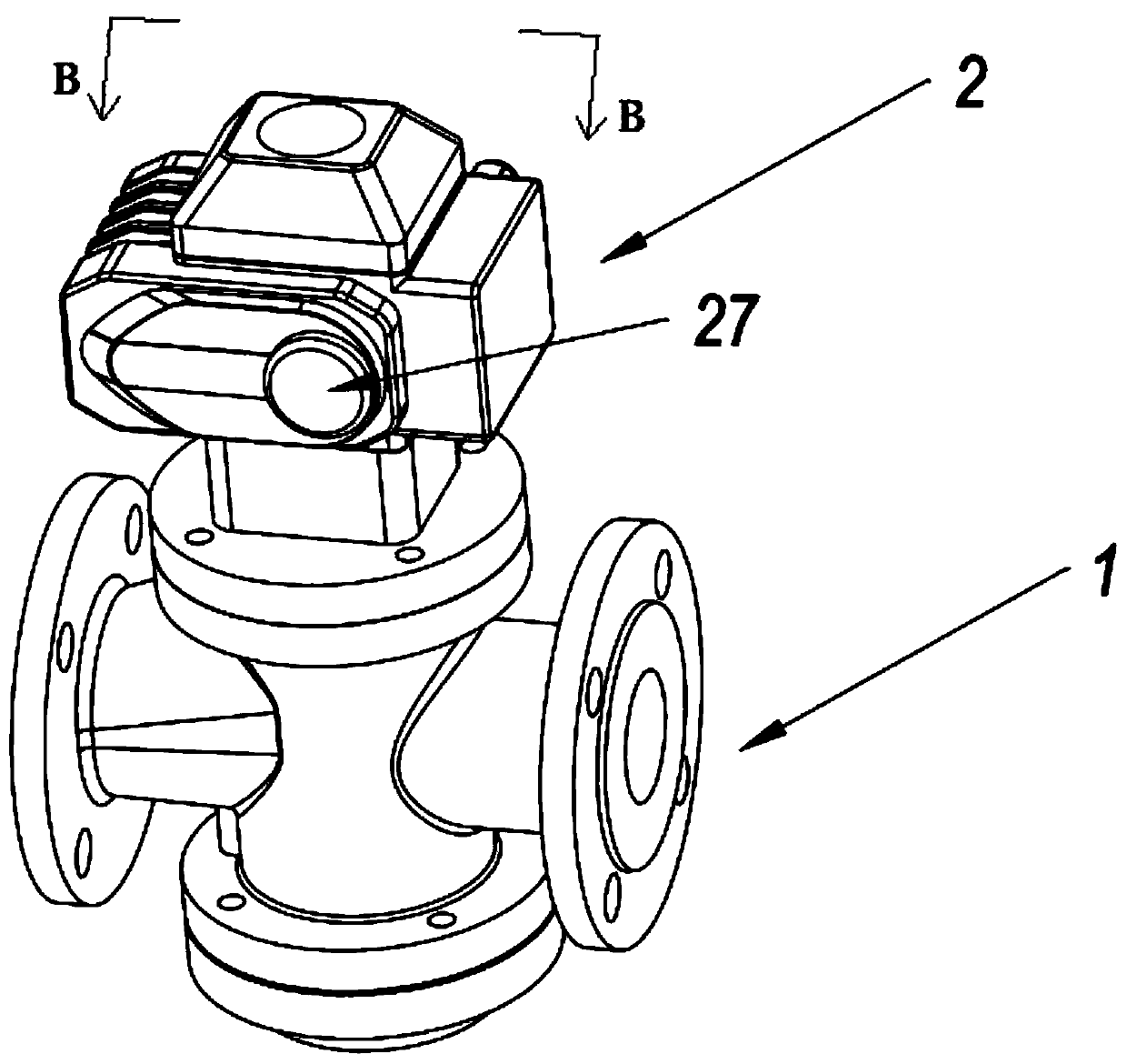
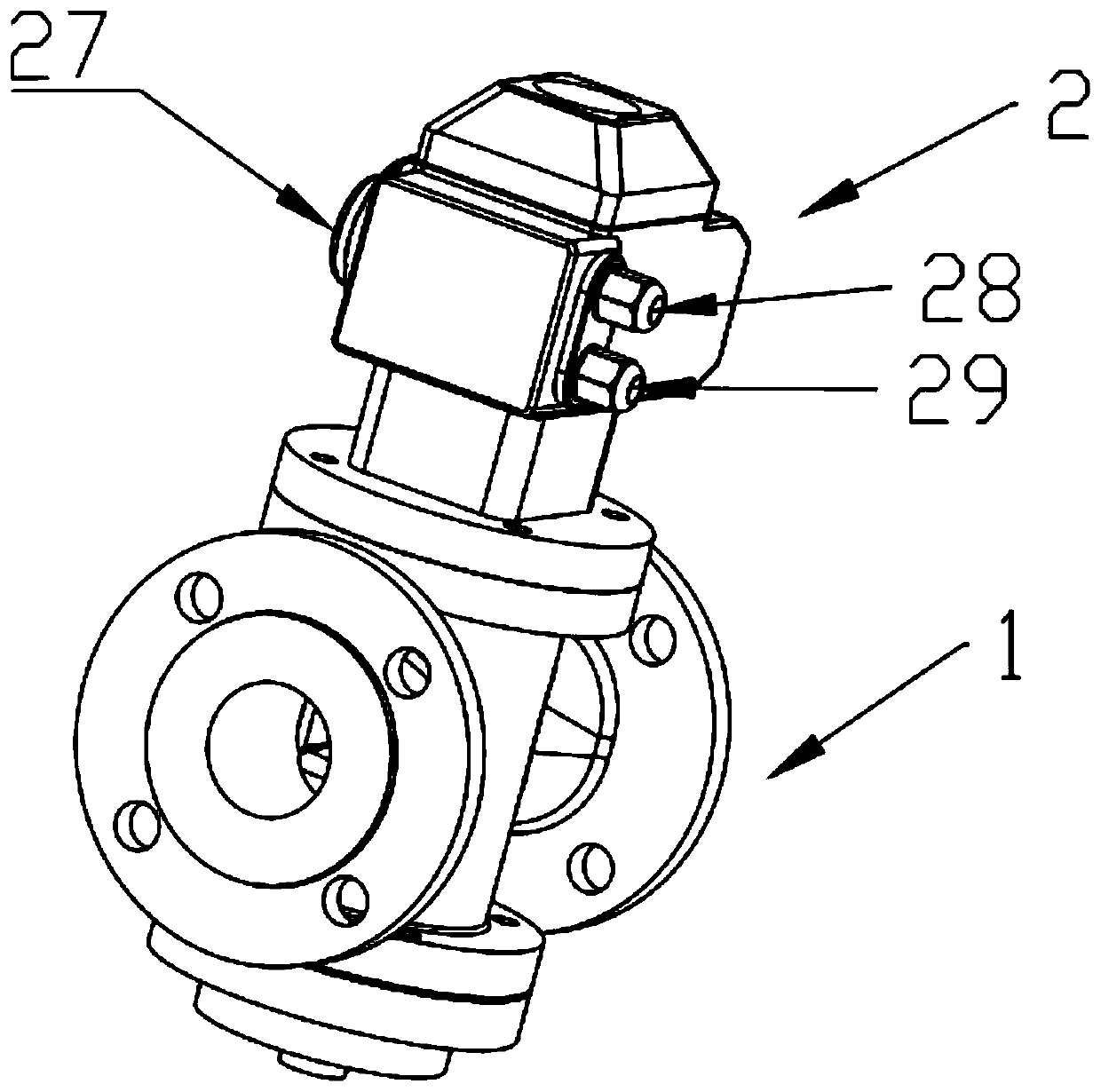
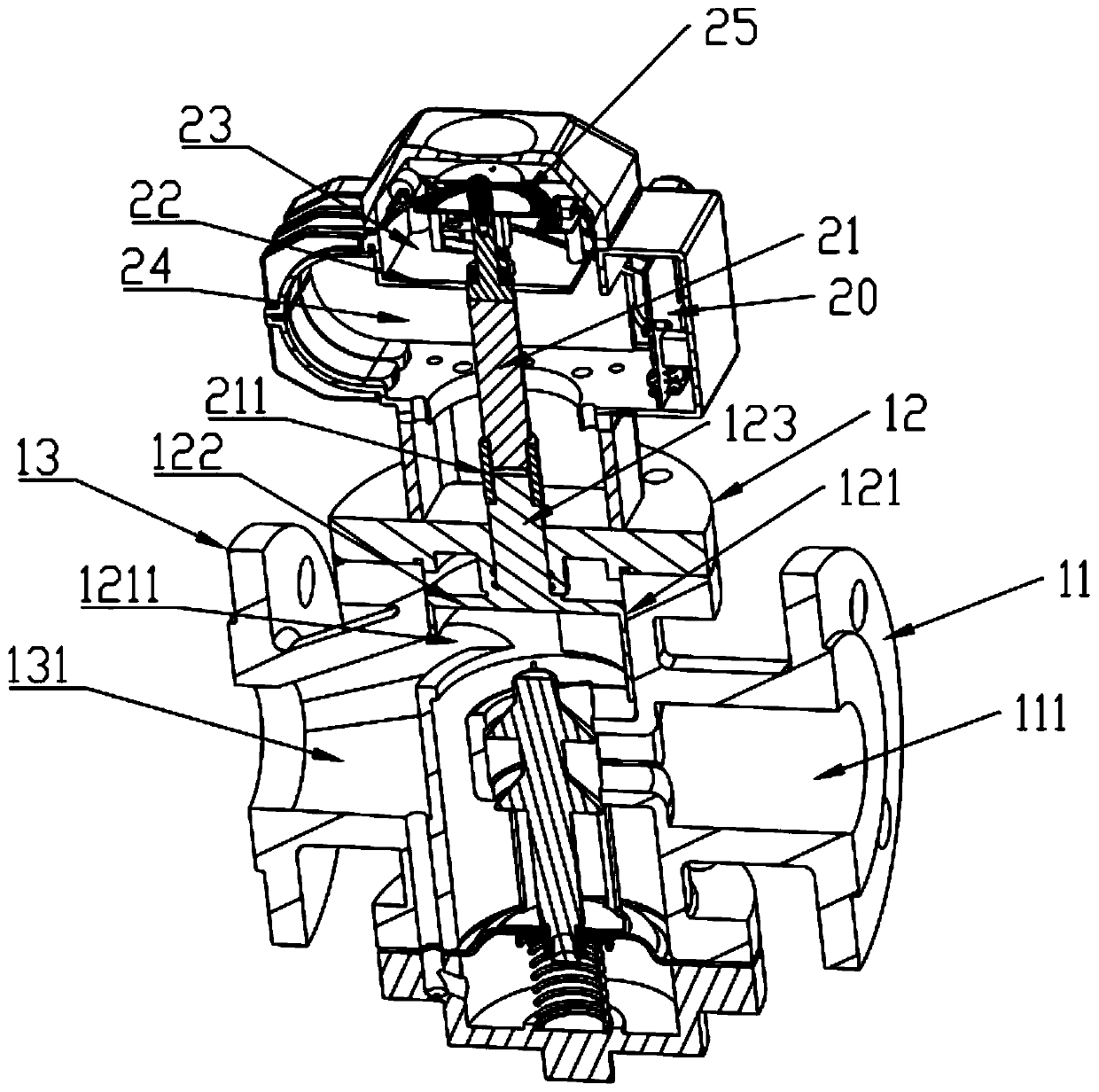
[0051] The present invention provides an intelligent heat distribution device, which includes a flow regulating valve 1 and an electric actuator 2 arranged on the flow regulating valve 1. The electric actuator 2 is used to control the opening of the internal valve of the flow regulating valve 1.
[0052] The flow regulating valve 1 includes a water inlet 11, a control unit 12 and a water outlet 13. The water inlet 11 is provided with a hollow water inlet cavity 111, the water outlet 13 is provided with a hollow water outlet cavity 131, and the control unit 12 is provided with The accommodating cavity 121 for accommodating the valve 122 and the control rod 123, the water inlet cavity 111 is in communication with the accommodating cavity 121, and the valve 122 is movably connected to the accommodating cavity 121. Preferably, the valve 122 and the control rod 123 are integrally connected, the valve A valve port 1211 is provided on the 122, and the accommodating cavity 121 and the water outlet cavity 131 are connected through the valve port 1211.
[0053] In actual use, fluid enters the flow regulating valve 1 through the water inlet cavity 111. Since the water inlet cavity 111 is connected to the containing cavity 121, the fluid enters the containing cavity 121. At this time, the valve 122 rotates when the control lever 123 is rotated, thus Drive the valve port 1211 to rotate. Because the position of the valve port 1211 is different, the opening of the valve port 1211 can be controlled, which affects the communication between the accommodating cavity 121 and the water outlet cavity 131, thereby controlling the flow of fluid. The fluid passes through the valve port 1211. It enters the water outlet cavity 131, and is finally discharged from the flow regulating valve 1 through the water outlet cavity 131.
[0054] The electric actuator 2 includes a controller arranged on the main control board 20, a drive shaft 21 fixedly connected to the control rod 123, a partition plate 22, a control cavity 23, a device cavity 24, and a grating for calculating the opening of the valve 122 Positioning device 25, the electric actuator 2 is provided with a control zone, the main control board 20 is vertically fixed in the control zone, the drive shaft 21 is fixedly connected with the control rod 123 through a coupling 211 and rotates synchronously, and the partition plate 22 drives the electric The interior of the actuator 2 is divided into a control cavity 23 and a device cavity 24. The control cavity 23 is above the device cavity 24, and the drive shaft 21 passes through the partition plate 22. Inside the control cavity 23 and the device cavity 24, the device cavity 24 is provided There is a motor fixedly connected to the drive shaft 21, the motor is electrically connected to the motor drive module on the main control board 20, and the controller is electrically connected to the motor drive module, so that the controller controls the motor through the motor drive module, thereby driving the rotation of the drive shaft 21 , The grating positioning device 25 is arranged in the control cavity 23, and is fixedly connected with the drive shaft 21, and can rotate synchronously with the drive shaft 21. The circuit schematic diagram of the motor drive module is as follows Figure 7 Shown.
[0055] The grating positioning device 25 includes a grating disc 251, a light-emitting element 252, a photosensitive element 253, and a pointer disc 254. The grating disc 251 is mounted on the drive shaft 21 in a radial direction, and is perpendicularly connected to the drive shaft 21, and can rotate synchronously with the drive shaft 21. In addition, the grating disc 251 is provided with a number of equally divided grid grooves. The light-emitting elements 252 and photosensitive elements 253 are respectively arranged on the upper and lower sides of the grating disc 251, and they are arranged symmetrically with respect to the grating disc 251, and the light-emitting elements 252 are parallel to the grating disc 251. And the light emitted by the light emitting element 252 can vertically pass through the grid groove of the grating disc 251, the photosensitive element 253 can receive the light emitted by the light emitting element 252 on the other side of the grating disc 251, and the light emitting element 252 and the photosensitive element 253 are both Electrically connected to the controller of the electric actuator 2, when the grating disc 251 rotates with the drive shaft 21, the light emitted by the light-emitting element 252 will be blocked by the grid grooves of the grating disc 251, and the photosensitive element 253 will receive the discontinuous Optical signal, the photosensitive element 253 converts the received optical signal into an electrical signal and transmits it to the controller, so that the controller can accurately grasp the stroke of the grid groove, and the grating disc 251 is fixedly connected to the drive shaft 21 and rotates synchronously, and the drive shaft 21 The control rod 123 is fixedly connected to the valve 122 and rotates synchronously, so the controller can accurately control the opening degree of the valve 122. A pointer is drawn on the pointer disk 254 and is fixedly connected to the driving shaft 21, and can rotate synchronously with the driving shaft 21. The pointer disk 254 is arranged above the grating disk 251, and the opening position of the valve 122 can be grasped by the pointer disk 254. It should be pointed out that in the present invention, the number of grid slots provided on the grating disk 251 is not limited, and the number of grid slots on the grating disk 251 can be replaced according to the accuracy of the valve 122 required in actual use. In this embodiment Preferably, the grating disc 251 is provided with 200 equally divided grid grooves, and the degree of rotation of one grid groove is 1.8 degrees, thereby accurately controlling the opening of the valve 122.
[0056] The electric actuator 2 includes a maximum opening detection device 26. The maximum opening detection device 26 includes a touch device 261 and a switch 262. The touch device 261 is fixedly connected to the drive shaft 21, and the touch device 261 can be synchronized with the drive shaft 21 Turning, the switch 262 is arranged in the control chamber 23 and on the partition plate 22. The switch 262 is a single-pole double-throw switch electrically connected to the controller, and the switch 262 is always open toward the direction of the drive shaft 21. When the touch device 261 does not press the switch 262, such as Figure 8 As shown, the switch 262 is at A and can form a closed circuit with the motor. The motor runs normally. When the touch device 261 rotates to a certain position with the drive shaft 21, the switch 262 can be pressed. At this time, the switch 262 is at B ,Such as Picture 9 As shown, if a closed loop cannot be formed, the motor stops rotating.
[0057] Preferably, the touch device 261 is provided with a protrusion 2611. Preferably, the touch device 261 and the protrusion 2611 are integrally connected. When the protrusion 2611 on the touch device 261 rotates with the drive shaft 21, the protrusion 2611 is not When you touch switch 262, such as Figure 8 As shown, the switch 262 is at A, which can form a closed circuit with the motor. The motor runs normally. When the protrusion 2611 rotates to the position corresponding to the switch 262, the switch 262 is pressed, as Picture 9 As shown, the switch 262 is at B and cannot form a closed circuit, the motor stops rotating, and at the same time, this is the position of the maximum opening of the valve 122.
[0058] In the internal structure of the switch 262, the switch 262 includes a housing 2621, a button 2622, a spring 2623, a lever 2624, a roller 2625, a movable contact 2626, a fixed contact 2627, and a terminal 2628. The outer end of the housing 2621 is provided with three terminals 2628. , Respectively, terminal a, terminal b, terminal c, the three can be connected to the external circuit respectively, the other end of the housing 2621 is provided with an outlet hole, the button 2622 passes through the outlet hole, one half is inside the housing 2621, and the other half is exposed in the housing Outside the 2621, one end of the spring 2623 is set in the housing 2621, under the button 2622, and is in contact with the button 2622, and the spring 2623 is connected to the terminal a, which is connected to the external circuit, and the other end of the spring 2623 is provided with a movable contact 2626, and one movable contact 2626 is provided on the upper and lower surfaces of the elastic sheet 2623. Two fixed contacts 2627 are provided in the housing 2621 at positions corresponding to the upper and lower movable contacts 2626, respectively corresponding to Figure 8 , Picture 9 Points A and B are the fixed contact A and the fixed contact B. The two fixed contacts 2627 are respectively connected to the terminal b and the terminal c, that is, the fixed contact A is connected to the terminal c, and the fixed contact B is connected to the terminal b. The outer end of the housing 2621 corresponding to the button 2622 is provided with a lever 2624. One end of the lever 2624 is fixed on the housing 2621 and is in contact with the button 2622. The other end of the lever 2624 is a free end and is away from the housing. 2621, a roller 2625 is fixedly connected to the free end, and the roller 2625 can rotate relative to the lever 2624.
[0059] In the normal state, one of the movable contacts 2626 is in contact with the fixed contact A, and the terminal c is connected to the external circuit, which is equivalent to the position of the switch 262 at A, forming a path with the motor. When the protrusion 2611 touches When the switch 262 is turned on, the roller 2625 is first touched. The roller 2625 is cylindrical, which can reduce the frictional force when the protrusion 2611 touches. Then the end of the lever 2624 away from the housing 2621 (the free end) moves closer due to the external force. The direction movement of the housing 2621, pressing the button 2622, makes the button 2622 move, and presses the elastic piece 2623. Due to the deformation of the elastic piece 2623, the movable contact 2626 at the other end of the elastic piece 2623 moves, so that the other movable contact 2626 and the fixed contact The phase B is in contact, and the terminal c is not connected to the external circuit, which is equivalent to the position where the switch 262 is at B. If the circuit is open, it cannot form a path with the motor and the motor stops rotating. When the protrusion 2611 does not press the switch 262, the free end of the lever 2624 is away from the housing 2621, and the button 2622 is provided with a spring. The button 2622 bounces away from the elastic piece 2623 and contacts the lever 2624. The elastic piece 2623 returns to the initial state and can be touched. Point 2626 is in contact with the fixed contact A and returns to the original position.
[0060] To ensure the effect of "when the protrusion 2611 touches the switch 262, the valve 122 is at the maximum opening position", the following pre-adjustment steps are required. Specifically, a fixing hole is provided on the touch device 261, and an external device such as Hand wheel, turn the hand wheel to turn the control rod 123 so that the valve 122 is opened to the maximum position, and then the drive shaft 21 and the control rod 123 are fixedly connected through the coupling 211, so that the two can rotate synchronously. The touch device 261 to the protrusion 2611 are pressed to the position of the switch 262. At this time, the touch device 261 is fixed to the drive shaft 21 through the screw in the fixing hole, so that the touch device 261 can rotate synchronously with the drive shaft 21 Finally, the pointer disc 254 is fixed on the drive shaft 21, the upper cover of the electric actuator 2 and the corresponding position of the pointer disc 254 are provided with scales, so that the scale value of the upper cover of the electric actuator 2 and the position pointed to by the pointer disc 254 The position where the protrusion 2611 touches the switch 262 and the maximum opening position of the valve 122 correspond to each other to complete the connection between the electric actuator 2 and the flow regulating valve 1. When the protrusion 2611 is driven When the shaft 21 rotates to the position corresponding to the switch 262 and the switch 262 can be pressed, the opening of the valve 122 is at the maximum opening position. At this time, the pointer 254 also points to the designated position, so that the electric actuator 2 The opening of the valve 122 is observed from the outside. Of course, according to actual needs, the maximum opening of the valve can also be set to the minimum opening of the valve, and the solution obtained by such simple transformation also belongs to the protection scope of the present invention.
[0061] The electric actuator 2 includes a manual adjustment part 27. The manual adjustment part 27 is equipped with a gearbox. The end of the gearbox is fixedly connected to the drive shaft 21. When the power is cut off, the grating positioning device 25 cannot work, you can insert it at the manual adjustment part 27 Hand wheel, turning the hand wheel to control the rotation of the reduction box, thereby controlling the rotation of the drive shaft 21, and adjusting the opening of the valve 122.
[0062] As mentioned above, the electric actuator 2 uses the grating positioning device 25 to accurately calculate the opening of the valve 122, but when the power is cut off, the grating positioning device 25 cannot work normally, you can insert a handwheel at the manual adjustment part 27 to control the valve 122 In addition, the present invention designs a maximum opening detection device 26. The maximum opening detection device 26 can accurately grasp the maximum (small) position of the valve 122 when the valve 122 is at any opening under any circumstances. As the initial position, the control accuracy of the opening degree of the valve 122 by the electric actuator 2 is further increased, and the opening degree of the valve 122 actually required is adjusted accurately.
[0063] The electric actuator 2 is provided with a position detection module, which includes a grating positioning module and a maximum opening detection module, both of which are electrically connected to the controller, and the grating positioning module is electrically connected to the grating positioning device 25 to control and monitor the grating positioning For the operation of the device 25, the maximum opening detection module is electrically connected to the maximum opening detection device 26 to control and monitor the operation of the maximum opening detection device 26.
[0064] The main control board 20 of the electric actuator 2 is provided with a communication module, which includes a wired communication module and a wireless communication module, both of which are electrically connected to the controller. The wired communication module is connected to the server through a data line. The communication module transmits the data in the electric actuator 2 to the server by wire. The wireless communication module can remotely transmit the data in the controller to mobile terminals such as servers or mobile phones. The server or mobile terminal can also use these two modules to separately The opening value of the flow regulating valve 1 is transmitted to the controller to control the rotation of the motor and adjust the opening of the flow regulating valve 1. The circuit schematic diagrams of the wired communication module and the wireless communication module are as follows: Picture 10 , Picture 11 Shown.
[0065] The side of the electric actuator 2 opposite to the manual adjustment part 27 includes a power connection part 28 and a parameter measurement part 29. One end of the parameter measurement part 29 uses a temperature sensor and/or a pressure sensor to measure the temperature and pressure of the fluid. The main control board A temperature measurement module and a pressure measurement module are provided on the 20. The temperature sensor and/or pressure sensor at one end of the parameter measurement part 29 are electrically connected to the controller through the temperature measurement module and the pressure measurement module. In the case of central heating, the temperature measurement module passes the temperature The sensor measures the water supply temperature and return water temperature of the fluid. The pressure measurement module measures the water supply pressure and return pressure of the fluid through the pressure sensor. The temperature measurement module and the pressure measurement module transfer the measured data to the controller, and then the communication module to the server , So that the heating company can monitor central heating related data to ensure heating safety. The circuit schematic diagrams of the temperature measurement module and the pressure measurement module are as follows Picture 12 , Figure 13 Shown.
[0066] One end of the power connection part 28 is connected to the power supply system, and the other end is electrically connected to the power supply module on the main control board 20. The power supply module supplies power to the controller and each module.
[0067] The specific embodiments of the present invention are described in detail above. For those skilled in the art, without departing from the principle of the present invention, several modifications and improvements can be made to the present invention, and these modifications and improvements also belong to the present invention. The protection scope of the invention claims.