Power line mounting assembly of fan heater and fan heater

A technology for installing components and power cords, applied in the field of power cord installation components and heaters, can solve problems such as hidden safety hazards, unfavorable efficient production of heaters, and complicated power cord installation processes, avoiding direct friction, stable and convenient installation. The effect of installation

Inactive Publication Date: 2019-06-07
GREE ELECTRIC APPLIANCES INC
View PDF5 Cites 1 Cited by
  • Summary
  • Abstract
  • Description
  • Claims
  • Application Information

AI Technical Summary

Problems solved by technology

[0004] However, on the one hand, due to the gap between the coil and the power cord, external water can easily enter the heater through the gap, which poses a safety hazard; The installation process of the wire is complicated, which is not conducive to the efficient production of the heater

Method used


Image

  • Power line mounting assembly of fan heater and fan heater
  • Power line mounting assembly of fan heater and fan heater
  • Power line mounting assembly of fan heater and fan heater

Examples


Embodiment Construction

[0039] Embodiment of the power cord installation assembly of the heater:

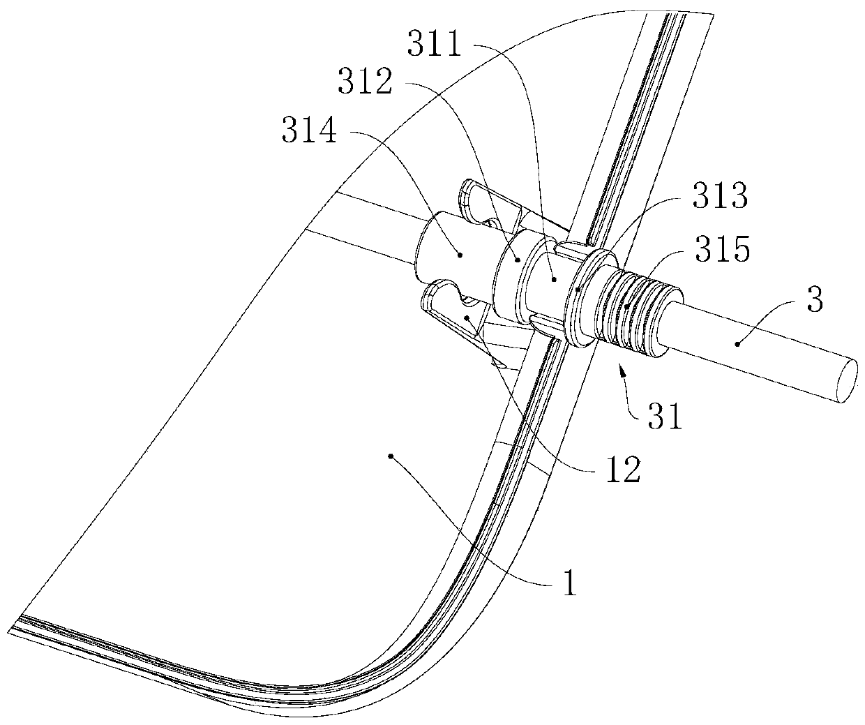
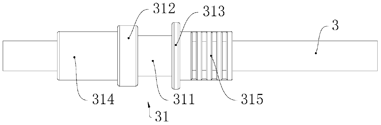
[0040] Please refer to Figure 1 to Figure 4 , this embodiment can be used for wall-mounted heaters. The power cord installation assembly of the air heater in this embodiment includes a first housing 1 , a second housing 2 and a power cord 3 .

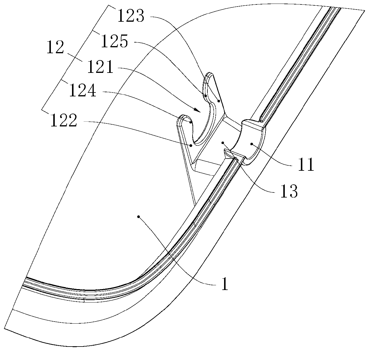
[0041] The first housing 1 is provided with a first half hole 11, a clip 12 and a first auxiliary positioning part 13 arranged between the first half hole 11 and the clip 12, the clip 12 and the first auxiliary positioning part 13 are both Located in the casing of the heater, the first auxiliary positioning part 13 is configured as a semi-circular shape, and the clips 12, the first auxiliary positioning part 13 and the first half hole 11 are distributed along a row.

[0042] The clip 12 has a first clip 122 and a second clip 123 arranged at intervals, one end of the first clip 122 is fixed to the first housing 1, the other end of the first clip 122 is a free e...


PUM


Abstract

The invention relates to the technical field of fan heaters, and provides a power line mounting assembly of a fan heater. The power line mounting assembly of the fan heater comprises a first shell, asecond shell and a power line, wherein a line outlet is formed between the first shell and the second shell; lantern rings are fixed to the circumferential wall of the power line, the lantern rings are provided with embedment parts and first positioning bulges which are abutted with each other, the embedment parts of the lantern rings are embedded into the line outlet, and the first positioning bulges are abutted with the inner wall of the first shell and/or the first positioning bulges are abutted with the inner wall of the second shell; and a clamp is arranged on the first shell, the clamp is located on the extension path of the line outlet, and the power line is clamped in a clamping groove of the clamp. The fan heater comprises the power line mounting assembly of the fan heater. The power line mounting assembly of the fan heater has the advantages of stability in installation of the power line, simple and quick installation process, the simple mounting structure and good water resistance.

Description

technical field [0001] The invention relates to the technical field of heaters, in particular to a power cord installation assembly of a heater and the heater. Background technique [0002] In the existing heater, the power cord passes through the outlet hole of the heater housing. In order to prevent the heater housing from damaging the power cord, the coil (flexible plastic rubber sleeve) is usually connected to the power cord jacket. The passing coil is embedded in the outlet hole, so that the passing coil is used to provide buffer between the power cord and the casing, so as to avoid direct contact and friction between the power cord and the casing. [0003] In order to prevent the power cord from moving along the axial direction of the outlet hole, the power cord is usually fixed in the heater housing; for example, a wire crimping clamp is used to compress and fix the wire, and the crimping clamp is installed on the housing by screws. [0004] However, on the one hand,...

Claims


Application Information

Patent Timeline
Patent Type & Authority Applications(China)
IPC IPC(8): F24H9/00
Inventor 陈跃王启龙石浩哲陈启荣张文达魏来
Owner GREE ELECTRIC APPLIANCES INC
Why Eureka
Try Eureka