Oil fume sampling detection device and sampling method thereof

A detection device and oil fume technology, which are applied in measurement devices, suspension and porous material analysis, particle suspension analysis, etc., can solve the problems of reducing oil fume measurement accuracy, weak signal light intensity, weak signal light, etc., and reduce external interference. , low cost and long service life

Inactive Publication Date: 2019-06-07
杭州明瑞智能检测科技有限公司
View PDF7 Cites 4 Cited by
  • Summary
  • Abstract
  • Description
  • Claims
  • Application Information

AI Technical Summary

Problems solved by technology

The oil fume detection device in the above-mentioned patent uses backscattering method to detect the oil fume. The device has the following disadvantages: 1. The stray light in the exhaust pipe easily interferes with the optical receiver, reducing the accuracy of the oil fume measurement; 2. The signal light generated by backscattering is weak, resulting in weak signal light intensity received by the optical receiver

Method used


Image

  • Oil fume sampling detection device and sampling method thereof
  • Oil fume sampling detection device and sampling method thereof
  • Oil fume sampling detection device and sampling method thereof

Examples


Embodiment 1

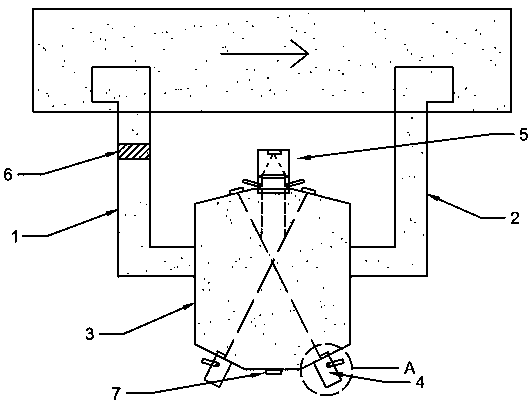
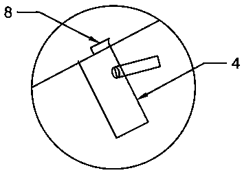
[0025] Embodiment 1: as figure 1 Shown is an oil fume sampling and detection device, including a light emitting module 4, a light receiving module 5, a processing module, an air inlet pipe 1, an air outlet pipe 2 and a sampling box 3, the processing module processes the signal received by the light receiving module 5, and the The sampling box 3 is located outside the smoke exhaust pipe, and is used to store and sample oil fume gas and install the light emitting module 4 and the light receiving module 5; one end of the air inlet pipe 1 is communicated with the exhaust pipe through a sampling hole, and the other end is communicated with the sampling box 3 , for fume gas to flow into the sampling box 3 from the exhaust pipe; one end of the outlet pipe 2 communicates with the sampling box 3, and the other end communicates with the exhaust pipe through a sampling hole, and is used for the fume gas to flow out from the sampling box 3 to the exhaust pipe. smoke pipes. Through the ab...

Embodiment 2

[0032] Embodiment 2: The basic structure of this embodiment is the same as that of Embodiment 1, and the difference is that the installation holes connecting the inlet pipe 1 and the outlet pipe 2 on the sampling box 3 are not on the same straight line (not drawn). That is, the setting of the installation holes on the sampling box 3 is not symmetrical. This design can make the oil fume gas introduced by the inlet pipe 1 change direction in the sampling box 3 before it can flow out from the outlet pipe 2, so that the oil fume gas can fully stay and diffuse, and the detection rate can be improved. the accuracy rate.

[0033] In addition, it also includes a sampling method of an oil fume sampling and detection device, which is suitable for the above-mentioned oil fume sampling and detection device, including the following steps:

[0034] S1: In the preparation stage, adjust the mesh aperture of the filter unit to 2 μm, turn on the fan blade exhaust fan to evacuate the large parti...


PUM


Abstract

The invention provides an oil fume sampling detection device and a sampling method thereof. The oil fume sampling detection device comprises an optical transmitting module, an optical receiving module, a processing module, an air inlet pipe, an air outlet pipe and a sampling box, the processing module processes a signal received by the optical receiving module, and the sampling box is located at the outside of a fume exhaust pipe and used for storing oil fume gas and mounting the optical transmitting module and the optical receiving module; one end of the air inlet pipe is communicated with the fume exhaust pipe, the other end of the air inlet pipe is communicated with the sampling box, and the air inlet pipe is used for enabling the oil fume gas to flow to the sampling box from the fume exhaust pipe; one end of the air outlet pipe is communicated with the sampling box while the other end thereof is communicated with the fume exhaust pipe, and the air outlet pipe is used for enabling the oil fume gas to flow out to the fume exhaust pipe from the sampling box. With the device and method provided by the invention, a process of detecting the oil fume gas is in a stable and sealed darkenvironment, interference of outside stray light on the optical receiving module is reduced to the minimum, and accuracy of oil fume detection is increased greatly.

Description

technical field [0001] The invention relates to the detection field of cooking fumes, in particular to a cooking fume sampling and detection device and a sampling method thereof. Background technique [0002] In the process of food cooking and processing, the organic matter of oil and ingredients is thermally decomposed or cracked, and the moisture in the ingredients is vaporized rapidly. Oil fume composed of sol, water vapor and fine particles. Oil fume not only directly endangers the health of the surrounding people, but also has become an important source of urban air pollution, and the use of oil fume detectors to accurately detect cooking fume is a necessary and basic link for controlling oil fume. [0003] China Patent Authorization Announcement No. CN 205481203 U, authorized announcement date August 17, 2016, discloses a laser oil fume sensing device for detecting the concentration of oil fume in the exhaust pipe, including: a light emitter for emitting a light sourc...

Claims


Application Information

Patent Timeline
Patent Type & Authority Applications(China)
IPC IPC(8): G01N15/06
CPCG01N15/06G01N2015/0693
Inventor 马颖杰牛军丽陈吕军陆志强
Owner 杭州明瑞智能检测科技有限公司
Why Eureka
Try Eureka