
A traveling wave tube multi-stage step-down collector

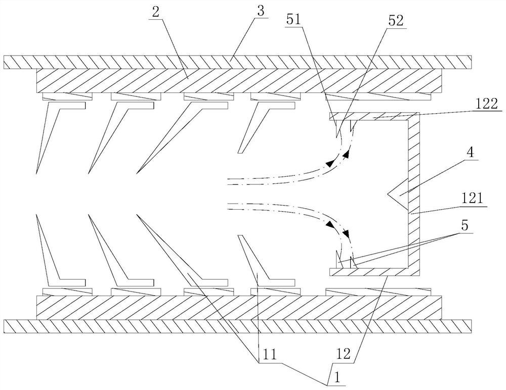
A collector and traveling wave tube technology, which is applied in the field of vacuum microwave electronic devices, can solve the problems of reduced life and reliability of the traveling wave tube, large local energy of the last stage collector, and low collection efficiency, so as to improve the heat dissipation effect and reduce the Reflux rate, the effect of increasing the bombardment area

Active Publication Date: 2021-02-02
NO 12 RES INST OF CETC
View PDF6 Cites 0 Cited by
  • Summary
  • Abstract
  • Description
  • Claims
  • Application Information

AI Technical Summary

Problems solved by technology

[0005] In view of the above problems, the technical problem to be solved by the present invention is to provide a traveling wave tube multi-stage step-down collector to solve the problem that the electron beam of the existing traveling wave tube multi-stage step-down collector directly bombards the final collector for a long time, resulting in The local energy of the final collector is too large, which reduces the life and reliability of the traveling wave tube, and due to the high backflow rate, the collection efficiency is low

Method used


Image

  • A traveling wave tube multi-stage step-down collector

Examples


Embodiment Construction

[0024] Various exemplary embodiments of the present invention will now be described in detail with reference to the accompanying drawings. It should be noted that the relative arrangements of components and steps, numerical expressions and numerical values ​​set forth in these embodiments do not limit the scope of the present invention unless specifically stated otherwise.

[0025] The following description of at least one exemplary embodiment is merely illustrative in nature and in no way taken as limiting the invention, its application or uses.

[0026] Techniques and devices known to those of ordinary skill in the relevant art may not be discussed in detail, but where appropriate, such techniques and devices should be considered part of the description.

[0027] In all examples shown and discussed herein, any specific values ​​should be construed as exemplary only, and not as limitations. Therefore, other instances of the exemplary embodiment may have different values.

...


PUM


Abstract

The invention discloses a traveling wave tube multi-stage step-down collector, which comprises an insulating porcelain cylinder with an inner cavity, an inner collector fixed in the inner cavity of the insulating porcelain cylinder, and an outer collector fixed on the outer wall of the insulating porcelain cylinder. collector; the inner collector includes a front-stage collector and a final collector; the final collector includes a body portion, and the body portion includes a bottom wall and a side wall; And the first conical protrusion coaxially arranged with the front-stage collector; the last-stage collector also includes a raised structure formed on the body; the raised structure includes a first formed on the inner wall surface of the side wall Biconical protrusions. The present invention solves the problem that the multi-stage step-down collectors of existing traveling wave tubes directly bombard the final collectors for a long time with electron beams, resulting in excessive local energy of the final collectors, which reduces the service life and reliability of the traveling wave tubes, and due to the return The problem of high flow rate and low collection efficiency.

Description

technical field [0001] The invention relates to the field of vacuum microwave electronic devices. More specifically, it relates to a traveling wave tube multi-stage step-down collector. Background technique [0002] With the development of space electronic technology, spaceborne synthetic aperture radar (SAR) satellites for remote sensing have become a research hotspot. Spaceborne SAR satellites can overcome the limitations of cloud, rain, snow and dark night conditions to image ground targets. All-weather, high-resolution, large-scale ground observation can play an important role in both military and civilian fields. As the core electronic device of spaceborne SAR radar, the high-power pulsed space traveling wave tube puts forward higher requirements on power, efficiency, reliability and other performances. [0003] In the development of existing traveling wave tubes, the efficiency requirements for airborne and ground high-power pulse traveling wave tubes are not high, a...

Claims


Application Information

Patent Timeline
Patent Type & Authority Patents(China)
IPC IPC(8): H01J23/027H01J23/033
Inventor 曹雪梅杨乐邵海丹
Owner NO 12 RES INST OF CETC
Learn More