Check patentability & draft patents in minutes with Patsnap Eureka AI!

Three-dimensional display

A three-dimensional display technology, applied in the field of 3D image display, achieves the effects of low cost, simple structure and convenient implementation

Pending Publication Date: 2019-06-11
张家港市地平线机电科技有限公司
View PDF0 Cites 5 Cited by
  • Summary
  • Abstract
  • Description
  • Claims
  • Application Information

AI Technical Summary

Problems solved by technology

[0003] The technical problem to be solved by the present invention is to overcome the deficiencies in the prior art, and provide a brand-new three-dimensional stereoscopic display for displaying real stereoscopic images at 360 degrees without dead angles. Meanwhile, the real stereoscopic images are not formed according to the binocular parallax effect. There will be no discomfort to the eyes, and there is no need for auxiliary equipment (such as 3D glasses) to watch. In addition, the lampposts do not block each other, so there will be no display blind spots

Method used


Image

  • Three-dimensional display
  • Three-dimensional display
  • Three-dimensional display

Examples


Embodiment 1

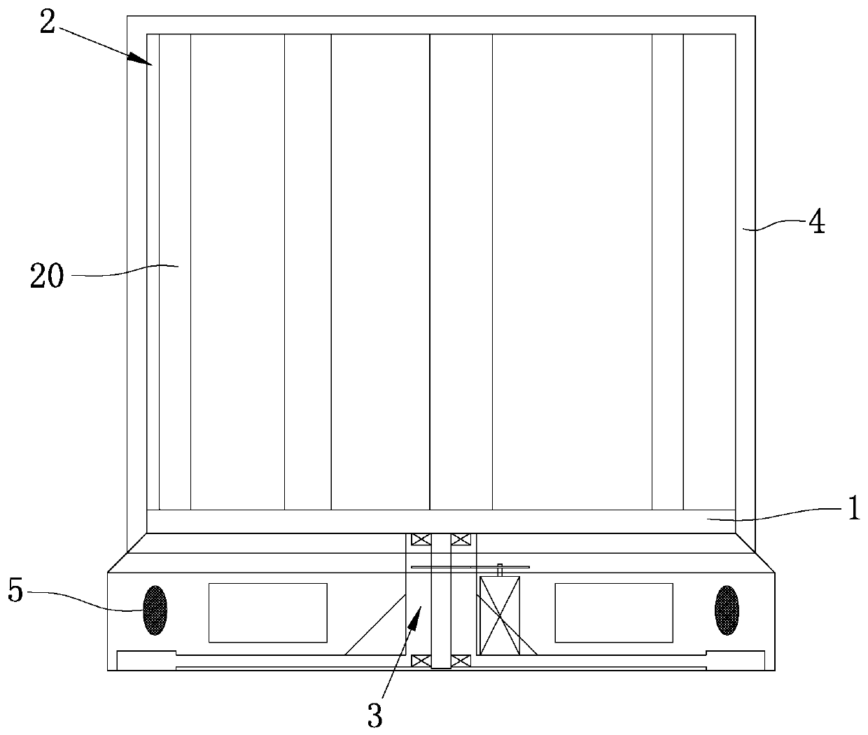
[0049] like figure 1As shown, according to this embodiment, the three-dimensional display includes a base 1, a lamp 2 arranged on the base 1, and a driving mechanism 3 for driving the base 1 to rotate around its own axis.

[0050] combine figure 2 As shown, the device seat 1 is in the shape of a disk, and track lines 10 are formed at uniform intervals along the radial direction of the disk.

[0051] combine image 3 As shown, the lamp 2 includes a plurality of lampposts 20 erected on the base 1 from the lower end, and a plurality of light bodies 21 evenly distributed on the lampposts 20 along the length direction of the lampposts 20, wherein the plurality of lampposts 20 They are relatively staggered and distributed on the base 1 without blocking each other; each light body 21 can be independently controlled to turn on or off.

[0052] Specifically, the lamp post 20 is straight and arranged vertically to the base 1, and the bright body 21 has three columns, such as Figur...

Embodiment 2

[0062] Such as Figure 5 to Figure 7 As shown, the structure of this embodiment is basically the same as that of Embodiment 1, the difference is that:

[0063] In this example, the layout of the lamp post 20, the diameter of the disc is 200mm, the height of each lamp post 20 is 200mm, it has 20 trajectory lines 10, and one lamp post 20 is distributed on each trajectory line 10, each There are 37 LED light-emitting components (one column) distributed on the lamppost 21, that is 740 in total.

[0064] At the same time, x=y=z=5.3mm, as for the layout of the lamp post 20 on the trajectory line 10 combined with the attached Figure 6 As shown, it is distributed in a helical state from the inside to the outside, and then turns to the Figure 6 indicated by the middle arrow.

Embodiment 3

[0066] Such as Figure 8a As shown, the structure of this embodiment is basically the same as that of Embodiment 1, the difference is that:

[0067] In this example, the lamp post 20 is arranged obliquely from bottom to top and inward, so that the three-dimensional display area formed by the voxel points formed by the light-emitting components is in the shape of a circular frustum.

[0068] see Figure 8b , the light-emitting components and the lamp post 20 form a transparent LED lamp strip.

[0069] At the same time, in this example, on the top of the LED light strip, a disc p similar to the device holder 1 is used, and the disc 23 is correspondingly provided with a track line, and the upper and lower ends of the LED light strip are respectively connected to the disc p and the device. On the trajectory line of the seat 1, here, the upper ends of multiple LED light strips are fixedly connected to prevent the LED light strips from moving during rotation, so as to enhance the ...


PUM


Abstract

The invention relates to a three-dimensional display. The display comprises a display base; a lamp including multiple lamp poles, and multiple lighting bodies uniformly distributed on the lamp poles along length directions of the lamp poles, wherein multiple lamp poles are relatively staggered and distributed on the display base in a non-shielding way, and each lighting body can be independently controlled to be turned on or off; a driving mechanism for driving the display base to rotate around the own axis or reciprocate on the plane; when the display base rotates or reciprocates, the lighting bodies on multiple lamp poles form a three-dimensional display area composed of multiple voxel points, and the multiple voxel points formed by the lighting bodies in the lighting state on each lamppoles form a three-dimensional entity. The real stereoscopic image displayed by the invention is not formed according to the binocular parallax effect, so that the uncomfortable problem is inexistentwhen watching the image through the human eyes, and the watching can be performed without using an auxiliary tool; and various lamp poles are free from shielding so that the display dead zone is inexistent.

Description

technical field [0001] The invention belongs to the field of 3D image display, and in particular relates to a three-dimensional display. Background technique [0002] At present, in the field of 3D display, the image to be displayed has a certain stereoscopic effect, that is to say, the provided image has a certain depth. The traditional helmet-mounted display can only provide the display information of a single virtual plane by eye. The binocular parallax effect makes the viewer produce a 3D depth of field effect, which can also be called a pseudo-stereoscopic image. Then, in order to see objects at different depths, the human eye needs to adjust the lens of the human eye so that the human eye focuses on this virtual plane In general, the greater the difference between the depth of the virtual object and the depth of the virtual plane, this will cause discomfort to the human eye. At the same time, due to the limitation of the viewing angle, many 3D images cannot be displaye...

Claims


Application Information

Patent Timeline
Patent Type & Authority Applications(China)
IPC IPC(8): G02B27/22
Inventor 顾金辉
Owner 张家港市地平线机电科技有限公司
Features
  • R&D
  • Intellectual Property
  • Life Sciences
  • Materials
  • Tech Scout
  • Unparalleled Data Quality
  • Higher Quality Content
  • 60% Fewer Hallucinations
Learn More