A display driving method of a liquid crystal display panel and the liquid crystal display panel

A liquid crystal display panel and display driver technology, applied in static indicators, instruments, etc., can solve the problems of large brightness gap and poor viewing experience, etc.

Active Publication Date: 2019-06-11
HEFEI BOE OPTOELECTRONICS TECH +1
View PDF20 Cites 13 Cited by
  • Summary
  • Abstract
  • Description
  • Claims
  • Application Information

AI Technical Summary

Problems solved by technology

[0006] The present invention at least partly solves the problem that the same display area of ​​the existing liquid crystal display panel has a large brightness difference between two adjacent frames, resulting in poor viewing experience, and provides a method that can reduce the difference between the same display area of ​​the liquid crystal display panel Brightness difference between two frames, display driving method of liquid crystal display panel and liquid crystal display panel for improving display effect

Method used


Image

  • A display driving method of a liquid crystal display panel and the liquid crystal display panel
  • A display driving method of a liquid crystal display panel and the liquid crystal display panel
  • A display driving method of a liquid crystal display panel and the liquid crystal display panel

Examples


Embodiment 1

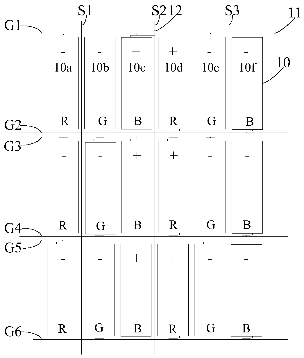
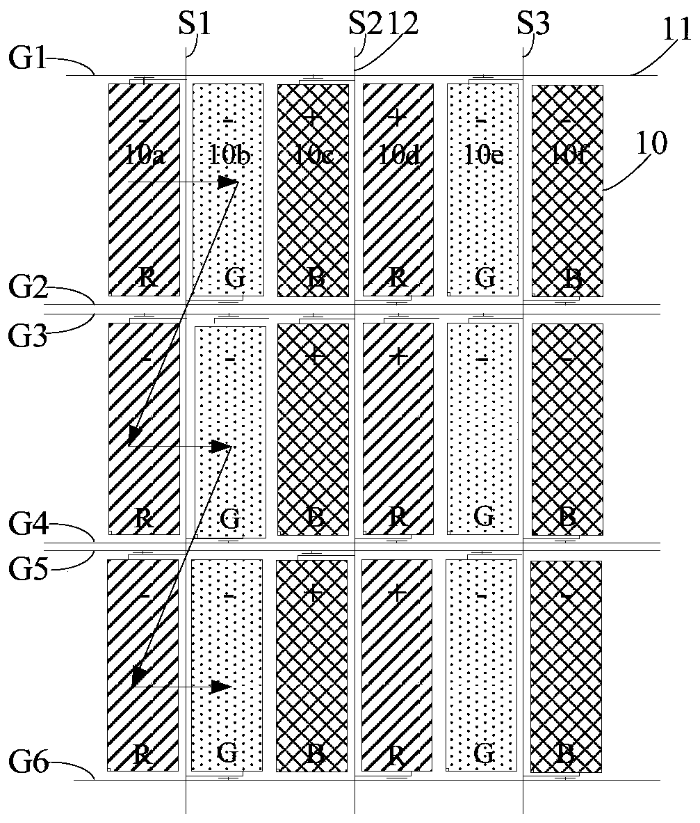
[0046] see Figure 2a , Figure 2b as well as image 3 , the present embodiment provides a display driving method of a liquid crystal display panel, for example, the method runs in the liquid crystal display panel to drive the display of the liquid crystal display panel, the liquid crystal display panel includes an array substrate, and the array substrate includes:

[0047] A plurality of sub-pixels 10 arranged in an array;

[0048] A plurality of gate lines 11 extending along the row direction, and a plurality of data lines 12 extending along the column direction;

[0049] Each sub-pixel 10 is electrically connected to a gate line 11 and a data line 12;

[0050]Any row of sub-pixels 10 corresponds to two gate lines 11 located on both sides thereof and adjacent to it, and the sub-pixels 10 therein are electrically connected to the two gate lines 11 in turn;

[0051] All columns of sub-pixels 10 are divided into multiple groups, each group is two columns of adjacent sub-pix...

Embodiment 2

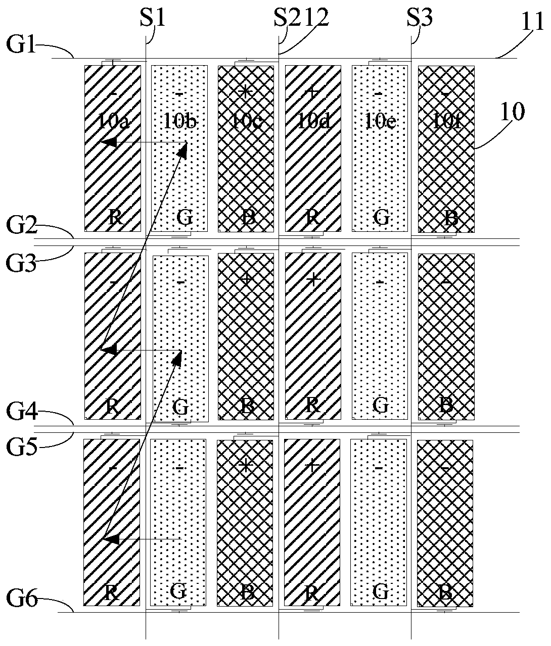
[0087] see Figure 2a , Figure 2b as well as image 3 , the present embodiment provides a liquid crystal display panel, comprising:

[0088] A plurality of sub-pixels 10 arranged in an array;

[0089] A plurality of gate lines 11 extending along the row direction, and a plurality of data lines 12 extending along the column direction;

[0090] Each sub-pixel 10 is electrically connected to a gate line 11 and a data line 12;

[0091] Any row of sub-pixels 10 corresponds to two gate lines 11 located on both sides thereof and adjacent to it, and the sub-pixels 10 therein are electrically connected to the two gate lines 11 in turn;

[0092]All columns of sub-pixels 10 are divided into multiple groups, each group is two columns of adjacent sub-pixels 10, and all sub-pixels 10 in any group are electrically connected to a data line 12 between the two columns of sub-pixels 10;

[0093] The liquid crystal display panel also includes a display drive unit, and the display drive unit...


PUM


Abstract

The invention provides a display driving method of a liquid crystal display panel and the liquid crystal display panel, which belong to the technical field of display, and can overcome the defect thatthe viewing experience is poor due to the fact that the brightness difference of the same display areas of an existing liquid crystal display panel in two adjacent frames is large. The display driving method of the liquid crystal display panel, for example, is applied to a double-grid type liquid crystal display panel and comprises the steps that in any frame picture, grid lines are conducted inturn, data signals are provided for the data lines, the polarities of the data signals provided for the same data line are not changed, and the polarities of the data signals provided for any two adjacent data lines are opposite; and in any two adjacent frames of images, the conduction sequences of the two grid lines corresponding to any row of sub-pixels are opposite, and the polarities of data signals provided for any data line are opposite.

Description

technical field [0001] The present invention relates to the field of display technology, in particular to a display driving method of a liquid crystal display panel and the liquid crystal display panel. Background technique [0002] The liquid crystal display panel includes a plurality of sub-pixels arranged in an array, and each sub-pixel is electrically connected to a gate line and a data line. When the gate line is turned on, the data signal on the data line can be written into the sub-pixel to control the LCD. The light transmittance achieves the display effect. [0003] In the related art, a dual gate line (Dual Gate Line) array substrate for liquid crystal display panels is proposed, see figure 1 , the array substrate includes a plurality of gate lines 11, namely the first gate line G1, the second gate line G2, the third gate line G3, the fourth gate line G4, the fifth gate line G5, the sixth gate line G6, and the grid The line 11 is insulated from multiple data line...

Claims


Application Information

Patent Timeline
Patent Type & Authority Applications(China)
IPC IPC(8): G09G3/36
Inventor 方志祥胡旭旭王猛丁鹏杨光磊
Owner HEFEI BOE OPTOELECTRONICS TECH
Why Eureka
Try Eureka