Seedling raising device for agricultural greenhouse
A technology for a seedling raising device and a greenhouse, which is applied in the field of agricultural seedling raising, can solve the problems of slow growth rate, poor applicability, white pollution, etc., and achieves the effects of lowering temperature, lowering oxygen concentration and slowing down respiration.
- Summary
- Abstract
- Description
- Claims
- Application Information
AI Technical Summary
Problems solved by technology
Method used
Image
Examples
specific Embodiment approach 1
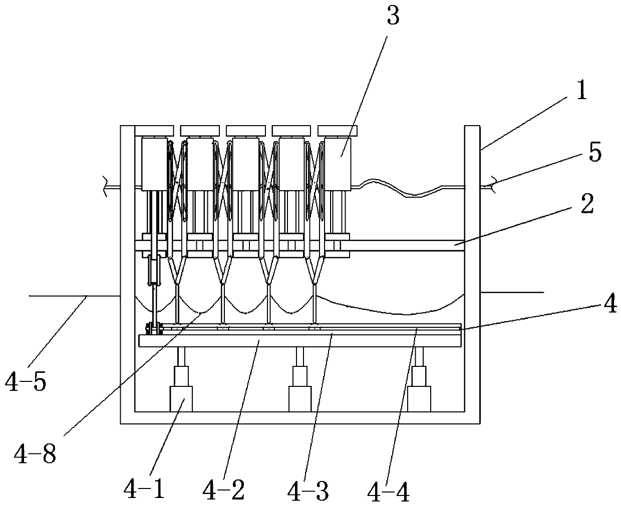
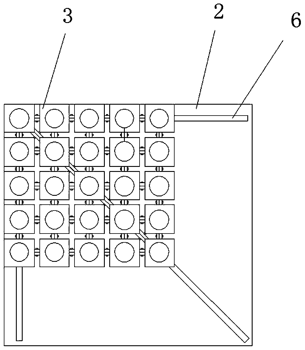
[0040] Such as figure 1 , 2 , 3, 4 and 9, a kind of agricultural greenhouse seedling raising device disclosed by the present embodiment comprises a seedling raising box 1, a fixed plate 2, a seedling raising display tray 3, a power unit 4 and a water supply device 5; in the seedling raising box 1 A fixed plate 2 is provided, the upper end of the fixed plate 2 is provided with a seedling raising display tray 3 and a water supply device 5, and the lower end is provided with a power device 4, and the fixed plate 2 is provided with three strip-shaped through holes 6, and one strip-shaped through hole 6 is along the The diagonal of the fixed plate 2 is arranged, and the other two strip-shaped through holes 6 are symmetrically arranged on both sides of the strip-shaped through-hole 6 arranged along the diagonal, and the included angle with the diagonal is 45 °, and the three strips The through-holes 6 meet in one place and are arranged in an arrow shape;
[0041] Such as figure 1...
specific Embodiment approach 2
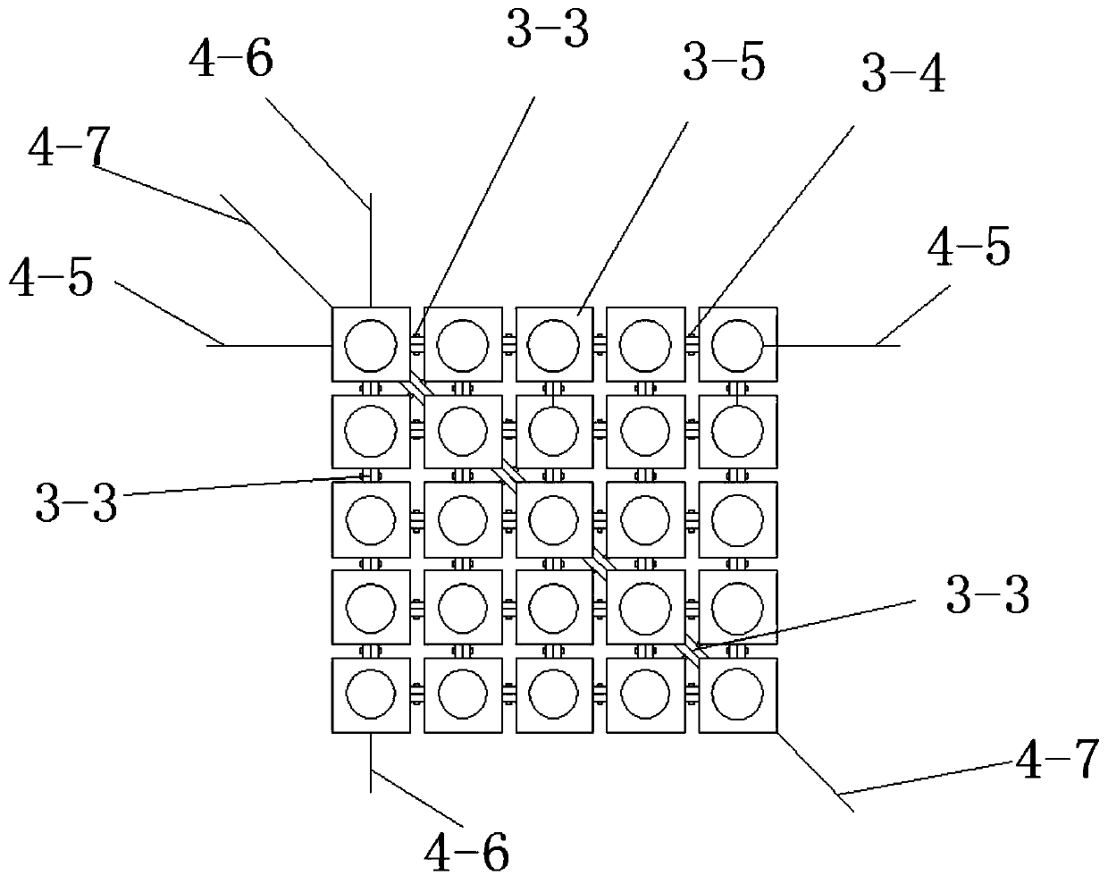
[0045] combine figure 1 , 5 , 6 and 7, this embodiment is based on the first specific embodiment, the difference is that the active connector 3-3 includes a long rod 3-3-1, a first rotating rod 3-3-3, The second rotating rod 3-3-4 and the roller 3-3-5; the long rod 3-3-1 is parallel and symmetrically arranged, and the outer wall is connected with the outer wall of the sleeve 3-1, and the long rod 3-3-1 There is a first bar-shaped chute 3-3-2 on the top, two first rotating rods 3-3-3 are arranged symmetrically through the rotating shaft, and one end of the first rotating rod 3-3-3 is arranged on a long rod through a pin shaft. In the first bar-shaped chute 3-3-2 on the 3-3-1, the other end is arranged in the first bar-shaped chute 3-3-2 on the other long rod 3-3-1 by a pin , the lower end of the long rod 3-3-1 passes through the strip-shaped through hole 6 on the fixed plate 2 and is connected with one end of the second rotating rod 3-3-4, and the other ends of the two second...
specific Embodiment approach 3
[0049] to combine figure 1 and 8 , this embodiment is based on the first specific embodiment, the difference is that the power device 4 includes a cylinder 4-1, a movable plate 4-2, a limit frame 4-3, a first traction rope 4-5, a second Two traction ropes 4-6 and the 3rd traction rope 4-7 and limit bead 4-8; The lower end faces of -2 are connected, the upper end face of the movable plate 4-2 is provided with a limit frame 4-3, and the limit frame 4-3 is arranged in an arrow shape, and the limit frame 4-3 arranged on the upper end face of the movable plate 4-2 is connected to the Corresponding to the bar-shaped through hole 6, the side wall of the limit frame 4-3 has a bar-shaped limit groove 4-4, and the roller 3-3-5 is symmetrical to the rod axis through the bar-shaped limit groove 4-4. Be arranged in the limit frame 4-3, one end of the transmission rod is arranged at the center of the rod shaft, one of the first traction rope 4-5 passes through the lateral side wall of the...
PUM
 Abstract
Description
Claims
Application Information
 - R&D
- Intellectual Property
- Life Sciences
- Materials
- Tech Scout
- Unparalleled Data Quality
- Higher Quality Content
- 60% Fewer Hallucinations
Browse by: Latest US Patents, China's latest patents, Technical Efficacy Thesaurus, Application Domain, Technology Topic, Popular Technical Reports.
© 2025 PatSnap. All rights reserved.Legal|Privacy policy|Modern Slavery Act Transparency Statement|Sitemap|About US| Contact US: help@patsnap.com


