Automatic material arranging device

An automatic discharging and clamping technology, applied in the field of capacitors, can solve the problems of affecting the transmission, the falling of the capacitor elements, and the unfixed capacitor elements on the conveyor belt, so as to ensure the stability and reliability, and avoid the effect of falling.

Pending Publication Date: 2019-06-14
SHENZHEN CHENGJIE INTELLIGENT EQUIP CO LTD
View PDF0 Cites 0 Cited by
  • Summary
  • Abstract
  • Description
  • Claims
  • Application Information

AI Technical Summary

Problems solved by technology

[0003] At present, the coiled capacitor element is generally placed on the conveyor belt and transported through the conveyor belt, but since the capacitor elemen

Method used


Image

  • Automatic material arranging device
  • Automatic material arranging device
  • Automatic material arranging device

Examples


Example Embodiment

[0033] The technical solutions in the embodiments of the present invention will be clearly and completely described below in conjunction with the accompanying drawings in the embodiments of the present invention. Obviously, the described embodiments are only a part of the embodiments of the present invention, rather than all the embodiments. Based on the embodiments of the present invention, all other embodiments obtained by those of ordinary skill in the art without creative work shall fall within the protection scope of the present invention.

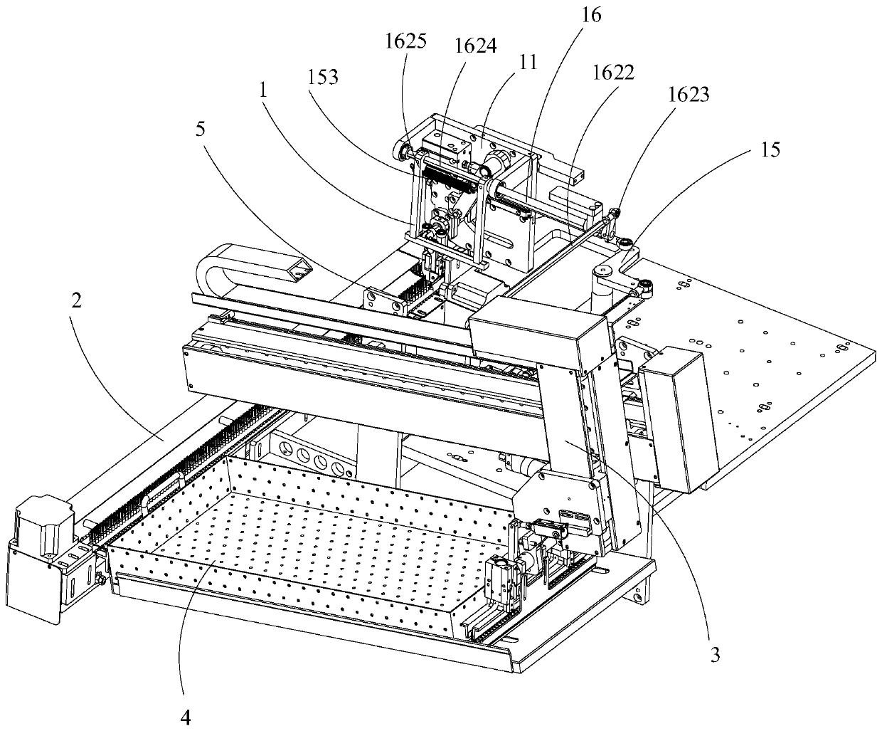
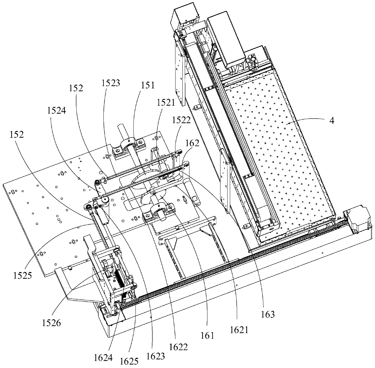
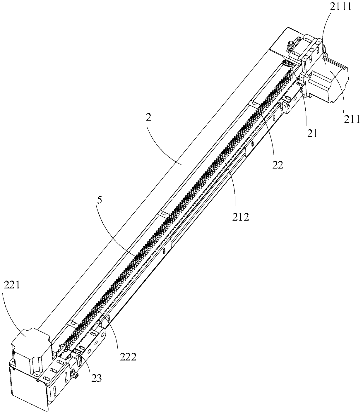
[0034] Such as figure 1 and image 3 As shown, the embodiment of the present invention provides an automatic discharging device, which includes a reclaiming mechanism 1, an arranging and conveying mechanism 2, and a discharging mechanism 3. The arranging and conveying mechanism 2 includes a first conveying line 21 and a second conveying line 22. The material mechanism 1 can transfer the capacitor element 5 to the first conveying line 21, ...


PUM


Abstract

The invention belongs to the technical field of capacitors, and relates to an automatic material arranging device. A material taking mechanism, an arranging and conveying mechanism and a discharging mechanism are included. The arranging and conveying mechanism comprises a first conveying line and a second conveying line. The material taking mechanism can convey capacitor elements to the first conveying line, and the second conveying line can generate magnetic attraction force so that the capacitor elements can be adsorbed and fixed. The first conveying line and the second conveying line can synchronously convey the capacitor elements. The discharging mechanism can convey the capacitor elements synchronously conveyed through the first conveying line and the second conveying line into carriers. According to the automatic material arranging device, the first conveying line plays a bearing role on the capacitor elements. The second conveying line generates magnetic attraction force so thatthe capacitor elements can be adsorbed and fixed to the second conveying line. The capacitor elements are subjected to the bearing action of the first conveying line and the magnetic attraction and fixing action of the second conveying line at the same time, and accordingly falling in the conveying process is avoided.

Description

technical field [0001] The invention relates to the technical field of capacitors, in particular to an automatic discharge device. Background technique [0002] A capacitor is a device that stores electrical charge and is widely used in electronic devices. The main structure of the capacitor includes a capacitor element made of aluminum foil, electrolytic paper and guide pin winding. [0003] At present, the coiled capacitor element is generally placed on the conveyor belt and transported through the conveyor belt, but since the capacitor element is not fixed on the conveyor belt, the capacitor element may fall from the conveyor belt during the transmission process, thereby affecting its Normal delivery. Contents of the invention [0004] Based on this, it is necessary to provide an automatic discharge device that can prevent the capacitor elements from falling during the transmission process. [0005] An embodiment of the present invention provides an automatic dischar...

Claims


Application Information

Patent Timeline
IPC IPC(8): B65G47/90B65G47/04B65G47/26B65G54/02
Inventor 谭国彪郭玉华张传东
Owner SHENZHEN CHENGJIE INTELLIGENT EQUIP CO LTD
Why Eureka
Try Eureka