Gripper

A clamper and rotating plate technology, applied in the mechanical field, can solve the problems of poor clamping effect and inability to achieve multi-directional grasping, and achieve the effect of simple structure and low energy consumption

Pending Publication Date: 2019-06-14
徐柏辰
View PDF10 Cites 10 Cited by
  • Summary
  • Abstract
  • Description
  • Claims
  • Application Information

AI Technical Summary

Problems solved by technology

However, due to the grasping force, this kind of clamp can only be closed along the relative directions of the two groups of rod clusters, the direction is fixed, the clamping effect is poor, and it is impossible to achieve multi-directional grasping

Method used


Image

  • Gripper
  • Gripper
  • Gripper

Examples


Embodiment 1

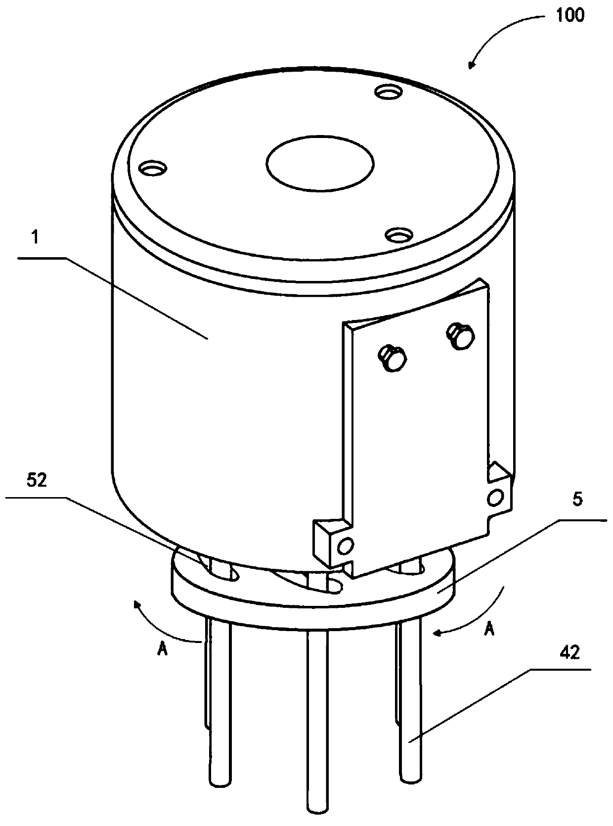
[0052] Embodiments of the present invention provide a holder, such as Figure 1 to Figure 9 As shown, the holder 100 includes: a base 1, a driving mechanism 2 provides a driving force; a rotating plate 5 is connected to the driving mechanism 2, and is driven to rotate by the driving force, and the rotating plate 5 is provided with at least three slide slots; at least three A fork 42, the first end of each fork 42 is rotatably connected with the base 1, and the second end of each fork 42 passes through a slide groove 52 respectively, and as the rotating plate 5 rotates, each fork 42 is guided by sliding grooves, wherein the number of sliding grooves can be greater than or equal to the number of swing bars 42 .

[0053] Specifically, as figure 1 As shown, three swing rods 42 are provided on the base 1 , wherein each swing rod 42 can rotate relative to the base 1 around the connection point between the swing rod 42 and the base 1 . Three slide slots 52 are arranged on the rotat...

Embodiment 2

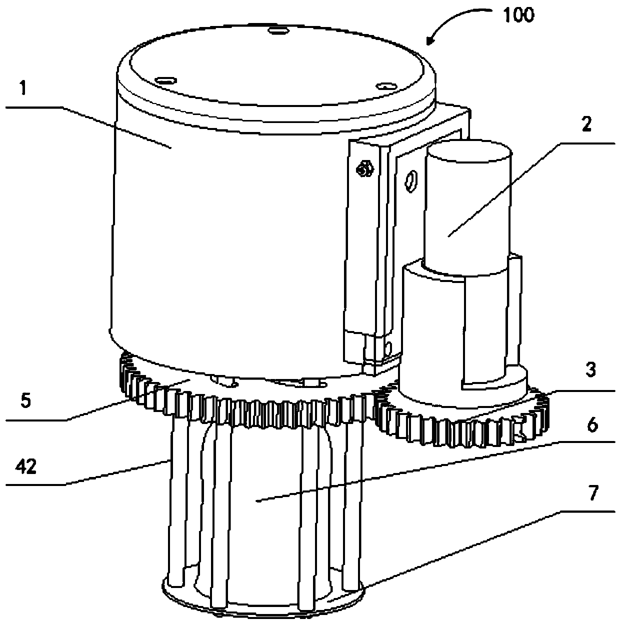
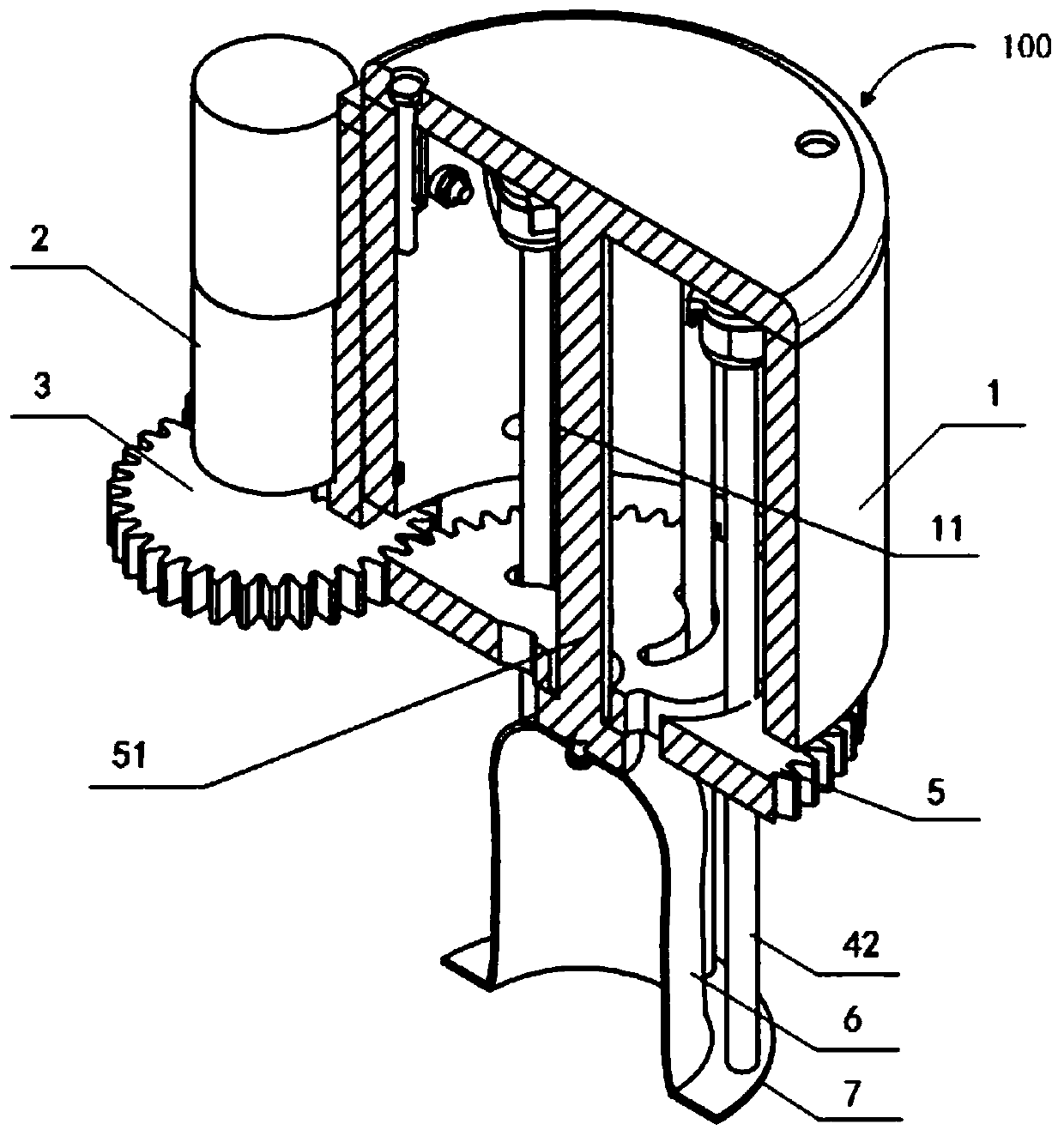
[0059] The difference with Embodiment 1 is that: on the basis of Embodiment 1, further, the clamper further includes: the clamper 100 also includes: a film cover 6, the edge of the film cover 6 and the first of at least three swing bars 42 The two ends are fixedly connected, and the top center of the film cover 6 is fixedly connected with the center of the rotating plate 5 . The film cover 6 is connected with at least three swing bars 42. When the swing bars 42 slide in the slide groove 52, the swing bars 42 gather or separate to drive the film cover 6 to shrink or open, as figure 2 and Figure 6 shown.

[0060] Preferably, the holder 100 further includes: an elastic member 7 fixedly connected with the edge of the film cover 6 and the swing bar 42 for gathering the edge of the film cover 6 . Similarly, when the swing rod 42 gathers or separates, the swing rod 42 can drive the elastic member 7 to contract or expand.

[0061] Such as Figure 6 to Figure 8 As shown, when the...

Embodiment 3

[0064] The difference from Embodiment 1 and Embodiment 2 is that: on the basis of Embodiment 1 or Embodiment 2, further, the clamper further includes: a transmission member 3, and a control device. The transmission part 3 is connected with the power output end of the driving mechanism 2 , and the output end of the transmission part 3 is connected with the rotating plate 5 . The control device is electrically connected with the driving mechanism 2, and is used to control the acting direction of the driving force, so that the rotating plate 5 can rotate in different radial directions, so as to achieve the purpose of automatically controlling the pendulum 42 to grab or release objects. Such as Figure 6 and Figure 7 As shown, the gripper 100 realizes the adjustment of the gripping speed and the gripping force control through the design of the transmission member 3 and the control of the driving mechanism 2 . In the case of the transmission member 3 , the driving force of the d...


PUM


Abstract

The invention provides a gripper, comprising a base, a driving mechanism, a rotating plate and at least three oscillating rod; the driving mechanism is used for providing a driving force; the rotatingplate is connected with the driving mechanism and is driven to rotate by the driving force; at least three sliding grooves are arranged in the rotating plate; the first ends of the oscillating rods are rotatably connected with the base and the second ends of the oscillating rods respectively pass through the corresponding sliding grooves; and with the rotation of the rotating plate, the oscillating rods are guided by the sliding grooves to move, and the number of the sliding grooves is more than that of the oscillating rods. The gripper provided by the invention can play a role in grasping objects from multiple directions, provide grasping forces to the objects in multiple directions and effectively grasp objects of any shapes placed in different directions. Furthermore, the gripper is not limited by the operation environment, low in energy consumption, simple in structure and convenient to operate.

Description

technical field [0001] The present invention relates to the field of machinery, and more specifically, relates to a clamper for clamping objects. Background technique [0002] Grippers are widely used in many fields such as robotics, logistics, and manufacturing. They are used for temporary connection and fixation of objects, and can be grasped or released at an appropriate time. The existing gripper generally has two groups of rod clusters, each group of rod clusters has a plurality of long rods parallel to each other, these long rods are set to adapt to the shape of the object, and then combined with the driving mechanism to drive the two groups of rod clusters Move closer or away to realize the grasping of the object. When the two groups of rod clusters gather together to clamp the object, the long rod is used to clamp the object from the side to achieve the purpose of grasping. However, due to the gripping force, this gripper can only be closed along the relative direc...

Claims


Application Information

Patent Timeline
Patent Type & Authority Applications(China)
IPC IPC(8): B65G47/90B23Q7/04B25J15/10
Inventor 徐柏辰张文增
Owner 徐柏辰
Why Eureka
Try Eureka