
Winding device of cable set on welding machine

A technology of a winding device and a welding machine, which is applied in the field of welding equipment, can solve the problems of inconvenient winding and finishing of the wire group, wear and tear of the wire group, etc.

Inactive Publication Date: 2019-06-14
陈丹虹
View PDF8 Cites 0 Cited by
  • Summary
  • Abstract
  • Description
  • Claims
  • Application Information

AI Technical Summary

Problems solved by technology

However, when the workpiece is large, the operator needs to constantly adjust the position of the welding torch, and because the workpiece is large in size, the length of the wire group connected to the welding torch on the welding machine is required to be large, and the longer wire group is dragged around with the welding torch, which is easy It causes the wire group to be worn, and it is not convenient to complete the wire group after welding.

Method used


Image

  • Winding device of cable set on welding machine
  • Winding device of cable set on welding machine
  • Winding device of cable set on welding machine

Examples


Embodiment

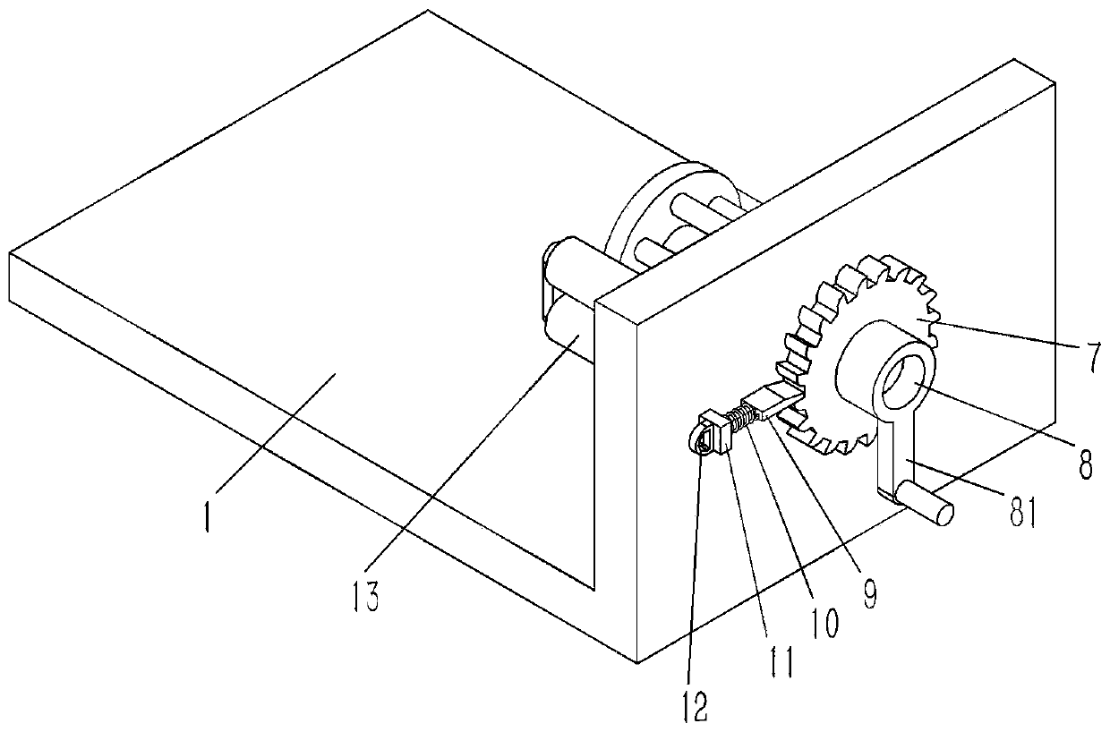
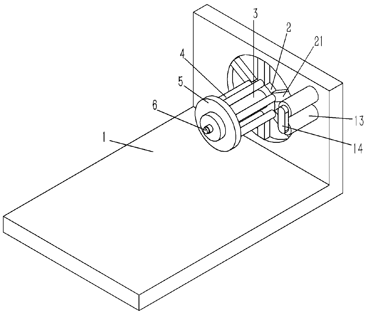
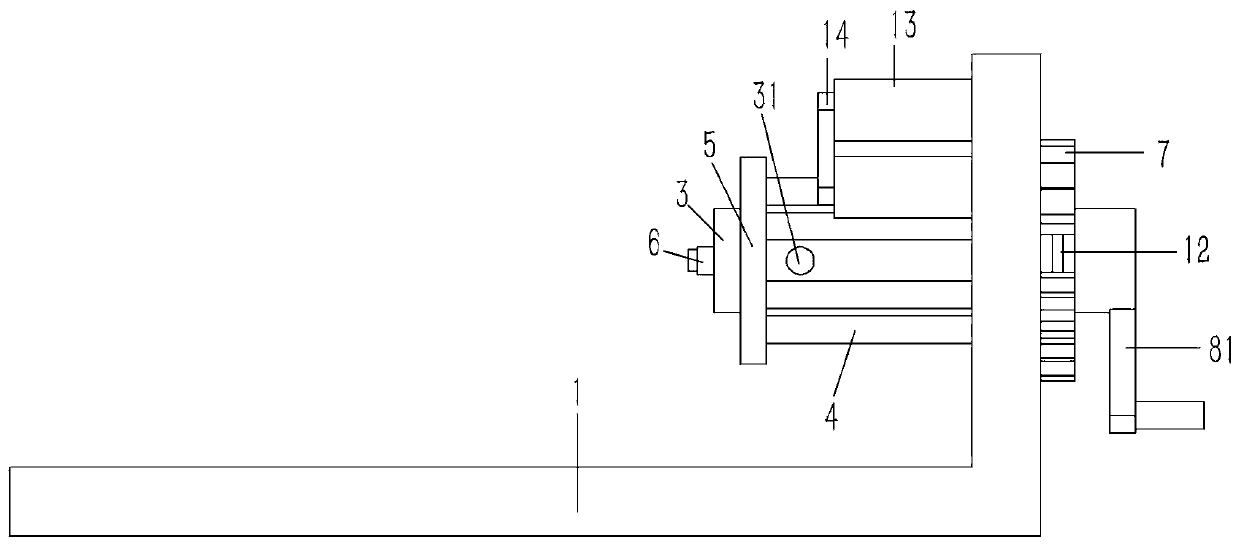
[0017] Example: see Figures 1 to 4 As shown, a winding device for the upper wire group of a welding machine includes an L-shaped supporting platform 1. The supporting platform 1 is composed of a horizontal plate and a vertical plate. The inner wall of the vertical plate of the supporting platform 1 is against a The annular inner retaining ring 2 has a plurality of spoke rods 21 formed on the outer wall of the inner retaining ring 2, and one end of the spoke rods 21 close to the inner retaining ring 2 is fixed with a winding rod 4, and the other end of the winding rod 4 is fixed on the annular outer ring. On the retaining ring 5, the inner retaining ring 2 and the outer retaining ring 5 are inserted and fixed on the T-shaped rotating shaft 3, and one end of the rotating shaft 3 is hinged on the vertical plate of the supporting platform 1 and passes through the supporting A ratchet 7 is fixed on the vertical plate sleeve of the platform 1, and a limit block 9 is inserted into t...


PUM


Abstract

The invention discloses a winding device of a cable set on a welding machine. The winding device comprises an L-shaped supporting table which comprises a horizontal plate and a vertical plate, whereinan annular inner check ring is leaned against the inner side wall of the vertical plate of the supporting table; a plurality of spoke bars are formed on the outer side wall of the inner check ring; awinding bar is fixed to one end, close to the inner check ring, of each spoke bar; the other end of each winding bar is fixed to an annular outer check ring; the inner check ring and the outer checkring are fixed to a T-shaped rotating shaft in an inserting and sleeving manner; one end of the rotating shaft is articulated on the vertical plate of the supporting table, passes through the verticalplate of the supporting table, and a ratchet wheel is fixed to the one end of the rotating shaft in an inserting and sleeving manner; a limited block is inserted in a tooth groove of the ratchet wheel; a supporting rod is formed on the limited block; the supporting rod on the limited block passes through a positioning block and is fixed to a pull ring; a compressed ring is sleeved on the supporting rod of the limited block in an inserting manner; the two ends of the compressed spring are respectively pressed against the limited block and the positioning block; an inserting hole penetrating the outer wall of the rotating shaft is formed in the end surface of the other end of the rotating shaft; and a cable set connector is inserted and fixed in the inserting hole of the end surface of therotating shaft. The winding device is convenient for completing the gathering and arrangement work of the welded cable set.

Description

Technical field: [0001] The invention relates to the technical field of welding equipment, and more specifically relates to a winding device for a wire group on a welding machine. Background technique: [0002] During the processing of sheet metal parts, multiple sheet metal parts need to be welded together, and welding is widely used as a processing and fixing method. Welding is a manufacturing process and technology for joining metals or other thermoplastic materials by means of heat, high temperature or high pressure. The welding process is usually completed with a welding machine. The welding machine uses the high-temperature arc generated when the positive and negative poles are short-circuited instantaneously to melt the solder on the welding wire and the material to be welded, so that the objects to be contacted are combined. At present, a welding torch is arranged on the welding machine, and the welding torch includes a handle and a spray head. The handle is the po...

Claims


Application Information

Patent Timeline
IPC IPC(8): B65H75/38B65H75/44
Inventor 陈丹虹
Owner 陈丹虹
Learn More