
Fabricated anti-flood wall

A flood wall and prefabricated technology, applied in dikes, breakwaters, coastline protection, etc., can solve the problems of large manpower and material resources, complicated on-site assembly, easy to be washed away, etc., to achieve simple construction and installation, good structural stability, and improved The effect of structural stability and impact resistance

Pending Publication Date: 2019-06-14
JINAN DONGYUAN CEMENT PROD CO LTD
View PDF0 Cites 0 Cited by
  • Summary
  • Abstract
  • Description
  • Claims
  • Application Information

AI Technical Summary

Problems solved by technology

The most primitive method of raising the height of the embankment is by stacking sandbags. Although it has good stability, the heightened embankment is called stable and is not easily destroyed by waves. Uneconomical, on the other hand, time is tight, and the rate of increase may not be able to reach the rate of rising water level, which is still a real danger
[0003] In order to quickly heighten the embankment, there are currently some prefabricated flood walls. There are two main types. One is the prefabricated flood wall made of aluminum alloy. Although the flood wall can meet the requirements of quick disassembly and assembly, it is not stable enough. , is easily washed out
The other is still made of concrete, but it is prefabricated in advance and assembled on site. Compared with the first type of aluminum alloy flood control wall, this kind of prefabricated flood wall has better stability, but it is heavy and bulky, which is inconvenient. Transportation and on-site assembly are also more complicated
[0004] Through the above analysis, it can be seen that stability and disassembly efficiency are a contradiction. To improve the disassembly efficiency, the stability must be sacrificed. To improve the stability, the volume and weight will inevitably be larger, which will make it difficult to disassemble. At present, there is no technical solution that can achieve both

Method used


Image

  • Fabricated anti-flood wall
  • Fabricated anti-flood wall
  • Fabricated anti-flood wall

Examples


Embodiment Construction

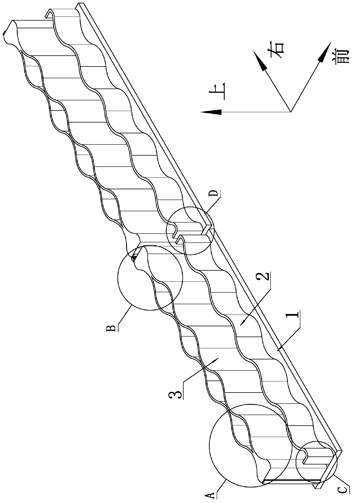
[0034] For the convenience of description, the coordinate system is defined as figure 1 shown.

[0035] Such as figure 1 As shown, a prefabricated flood wall includes several flood wall monomers, and several flood wall monomers are sequentially connected by connecting structures to form a continuous wall.

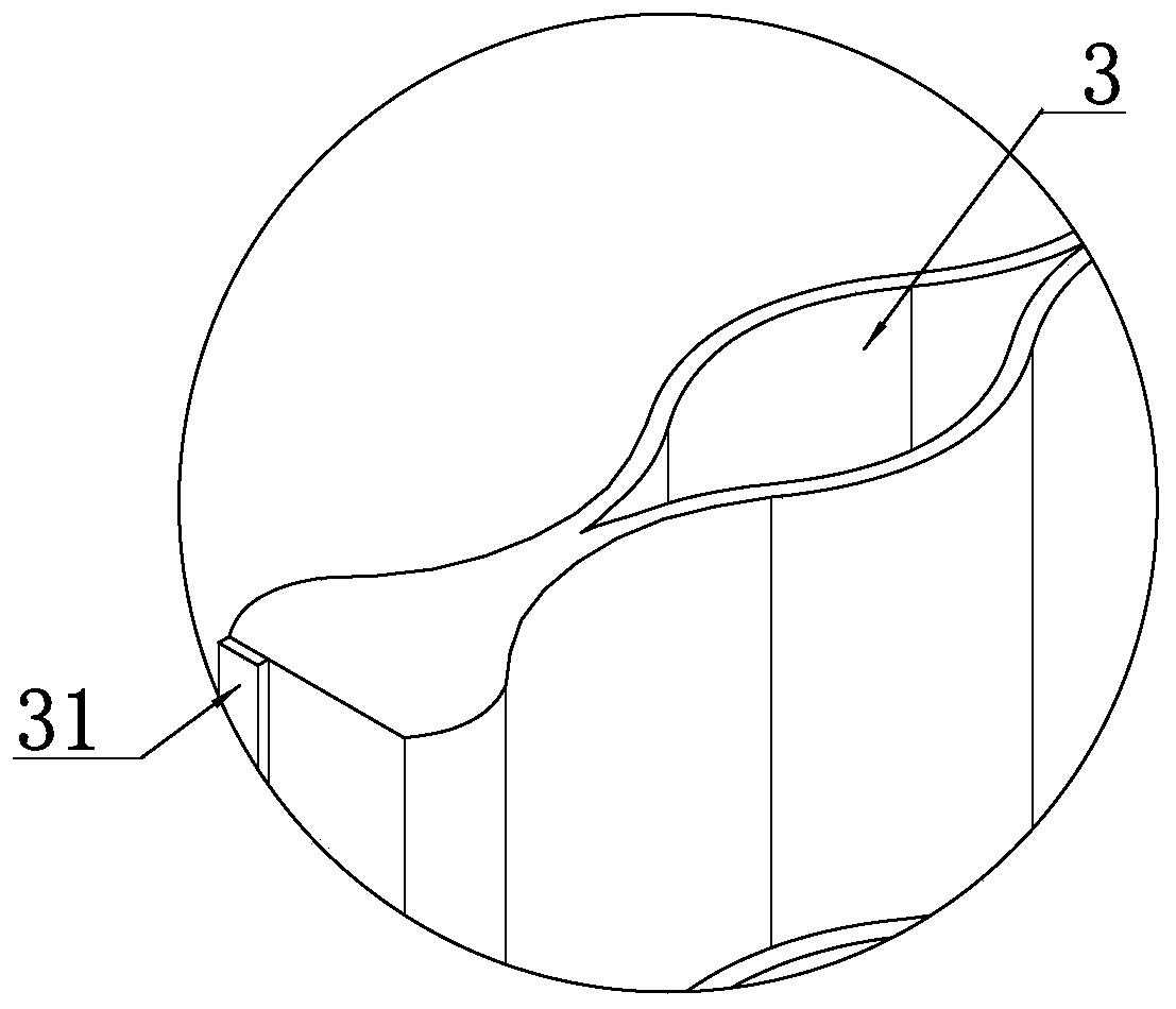
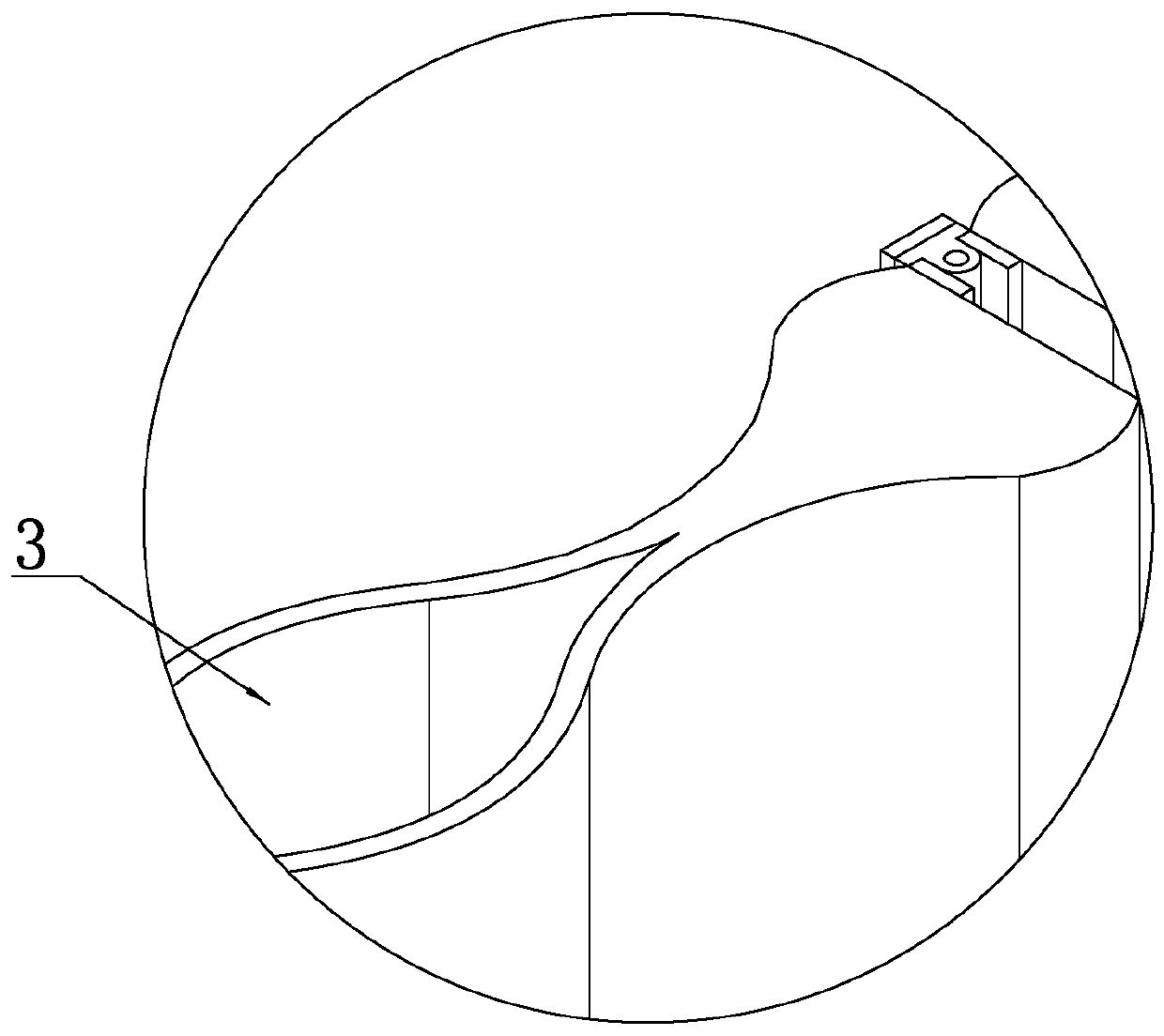
[0036] Such as figure 1 As shown, the flood control wall monomer includes a base plate 1, and a water retaining wall 2 with a wavy curved surface is arranged on the base plate 1, and a wave wall 3 is arranged on the rear side of the water retaining wall 2, A water storage area is formed between the wave break wall 3 and the water retaining wall 2 .

[0037] As a specific implementation, in this embodiment, the height of the retaining wall 2 is 1 meter, the height of the anti-wave wall 3 is 2 meters, and the width of the water storage area is 0.6 meters.

[0038] Such as Figure 6 and Figure 7 As shown, the left and right ends of the wave-proof wall 3 are respectively...


PUM


Abstract

The invention discloses a fabricated anti-flood wall. A plurality of anti-flood wall units are sequentially connected to form the anti-flood wall, the anti-flood wall units include foundation slabs, wherein water retaining walls are arranged on the foundation slabs, anti-wave walls are arranged on the rear sides of the water retaining walls, and a water storage area is formed between the anti-wavewalls and the water retaining walls. First steel plates are correspondingly arranged at the left ends and the right ends of the anti-wave walls, second steel plates are arranged between the two adjacent anti-wave wall units, and the second steel plates are correspondingly and fixedly connected with the two first steel plates. The front side walls and the rear side walls of the anti-wave plates are in wave shapes and are distributed symmetrically, and a plurality of hollow cavities which do not communicate with each other are formed through the front side walls, the rear side walls, the left side walls and the right side walls of the anti-wave walls. The anti-flood wall has sufficient stability and can be quickly disassembled and assembled, and stability and the efficiency of disassembly and assembly are both achieved.

Description

technical field [0001] The invention relates to the technical field of water conservancy facilities, in particular to an assembled flood wall capable of quick disassembly and assembly. Background technique [0002] When a flood disaster occurs, how to quickly consolidate the dam is the key to ensuring the safety of people's property. The most primitive method of raising the height of the embankment is by stacking sandbags. Although it has good stability, the heightened embankment is called stable and is not easily destroyed by waves. Uneconomical, on the other hand, time is tight, and the speed of possible heightening cannot reach the speed of rising water level, which still has real danger. [0003] In order to quickly heighten the embankment, there are currently some prefabricated flood walls. There are two main types. One is the prefabricated flood wall made of aluminum alloy. Although the flood wall can meet the requirements of quick disassembly and assembly, it is not ...

Claims


Application Information

Patent Timeline
IPC IPC(8): E02B3/10E02B3/06
Inventor 陈楠陈红卫
Owner JINAN DONGYUAN CEMENT PROD CO LTD
Learn More