AI technical title is built by Patsnap AI team. It summarizes the technical point description of the patent document.
A solar device and solar panel technology, applied in the field of solar energy, can solve the problems that solar devices are easy to accumulate dirt and have no dirt cleaning device
Active Publication Date: 2020-11-20
义乌市思淇工业设计有限公司
View PDF7 Cites 0 Cited by
Summary
Abstract
Description
Claims
Application Information
AI Technical Summary
This helps you quickly interpret patents by identifying the three key elements:
Problems solved by technology
Method used
Benefits of technology
Problems solved by technology
[0002] For example, the patent No. is CN201520028990.X, a kind of solar energy device, including an emptying device, installed on a water tank, and the water tank is provided with a water delivery pipe for transporting water, including an emptying pipe, an emptying check valve, a fixed ring, a water inlet pipe, Water inlet check valve, conduit and outlet pipe, the emptying pipe is installed in the inner cavity of the water tank, the lower end of the emptying pipe is connected to the water delivery pipe, the upper end is fixed on the water tank, and communicated with the outside atmosphere, the emptying check valve is installed in the drain At the upper end of the empty pipe, the conduction direction of the emptying check valve is the direction of entering the emptying pipe from the upper end of the water tank. It is located in the inner cavity of the emptying pipe, and the bottom end passes through the through hole and is fixed on the fixed ring. The water inlet check valve is installed in the inner cavity of the water inlet pipe, and the two ends of the conduit are connected to the water inlet pipe and the water tank. The walls are sealed, the conduction direction of the water inlet check valve is from the inner cavity of the water inlet pipe to the inner cavity of the water tank, and the outlet pipe is connected between the water tank and the water delivery pipe, but the disadvantage of this invention is that there is no dirt cleaning device , solar installations tend to accumulate dirt
Method used
Image
Click on the blue label to locate the original text in one second.
Reading with bidirectional positioning of images and text.
Examples
specific Embodiment approach 1
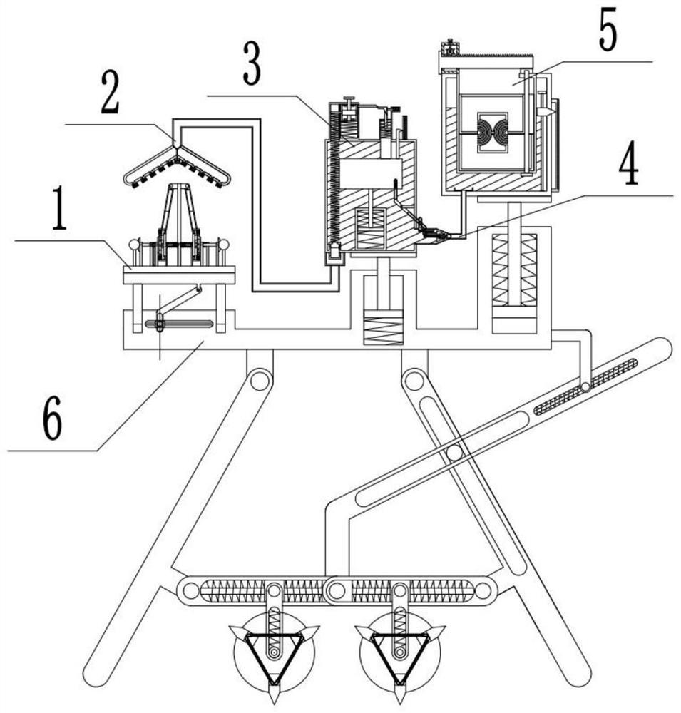
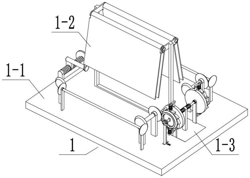
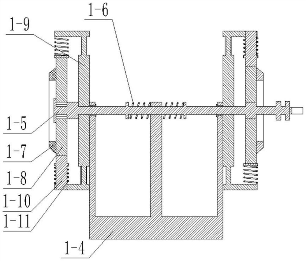
[0048] Combine below Figure 1-27Describe this embodiment, a solar energy device, including a solar panel fixing device 1, a nozzle device 2, a flow control box 3, a communication pipe 4, a water tank 5 and a bracket 6, and the solar panel fixing device 1 includes a bottom plate 1-1, Two fixed plates 1-2, adjusting device 1-3, adjusting bracket 1-4, manual rotating rod 1-5, rotating rod sleeve spring 1-6, two outer drive bevel teeth 1-7, two one-way Gear 1-8, two one-way drive gears 1-9, one-way slide bar 1-10, slide bar sleeve spring 1-11, handle 1-12, turning slot 1-13, two card bodies 1-14, Two limit plates 1-15, right limit plate 1-16, installation groove 1-17, pole one 1-18, pole two 1-19, pole three 1-20, pole four 1- 21. Five poles 1-22, six poles 1-23, seven poles 1-24, transmission straight teeth one 1-25, two-way threaded rods 1-26, transmission bevel teeth one 1-27, transmission straight teeth two 1-28, transmission rod one 1-29, transmission bevel gear three 1-30...
specific Embodiment approach 2
[0058] Combine below Figure 1-27 This embodiment will be described, and this embodiment will further describe the first embodiment, the two card bodies 1-14 are not connected to the two one-way gears 1-8 at the same time.
specific Embodiment approach 3
[0060] Combine below Figure 1-27 This embodiment will be described, and this embodiment will further describe Embodiment 1. The two-way threaded rod 1-26 is provided with thread lines with opposite directions of rotation.
PUM
Abstract
The invention relates to the field of solar energy, in particular to a novel solar energy device. The using angle of the solar energy device is changed through a solar energy panel fixing device; thesolar energy device is cleaned through a nozzle device; the water flow rate of the nozzle device is controlled by a flow rate control box; and water used for cleaning is filtered by a water box. The novel solar energy device comprises the solar energy panel fixing device, the nozzle device, the flow rate control box, a communicating pipe, the water box and a bracket. Two clamping bodies are asynchronously connected with two one-way gears, a manual rotating rod is pushed manually, and when the clamping body at the left end of the manual rotating rod is in fit with the one-way gear at the left end, the clamping body at the right end of the manual rotating rod is not in fit with the one-way gear at the right end; the clamping bodies are conveniently connected between the manual rotating rod and the one-way gears; and a plug makes downward movement under the action of the water pressure, and a plug connecting rod connected between the plug and a side wall rod pushes to allow the side wallrod to be separated from a closed groove, so that a water flow is discharged conveniently.
Description
technical field [0001] The invention relates to the field of solar energy, in particular to a solar energy device. Background technique [0002] For example, the patent No. is CN201520028990.X, a kind of solar energy device, including an emptying device, installed on a water tank, and the water tank is provided with a water delivery pipe for transporting water, including an emptying pipe, an emptying check valve, a fixed ring, a water inlet pipe, Water inlet check valve, conduit and outlet pipe, the emptying pipe is installed in the inner cavity of the water tank, the lower end of the emptying pipe is connected to the water delivery pipe, the upper end is fixed on the water tank, and communicated with the outside atmosphere, the emptying check valve is installed in the drain At the upper end of the empty pipe, the conduction direction of the emptying check valve is the direction of entering the emptying pipe from the upper end of the water tank. It is located in the inner c...
Claims
Application Information
Patent Timeline
Application Date:The date an application was filed.
Publication Date:The date a patent or application was officially published.
First Publication Date:The earliest publication date of a patent with the same application number.
Issue Date:Publication date of the patent grant document.
PCT Entry Date:The Entry date of PCT National Phase.
Estimated Expiry Date:The statutory expiry date of a patent right according to the Patent Law, and it is the longest term of protection that the patent right can achieve without the termination of the patent right due to other reasons(Term extension factor has been taken into account ).
Invalid Date:Actual expiry date is based on effective date or publication date of legal transaction data of invalid patent.

