Stope overlying rock separation layer monitoring method based on optical fiber

A technology of overburden detachment and optical fiber, which is applied in the field of overburden detachment monitoring based on optical fiber, can solve the problem of inability to determine the size change and development law of overlying detachment in the stope, small monitoring range, and small overburden movement And other issues

Inactive Publication Date: 2019-06-14
SHANDONG UNIV OF SCI & TECH
View PDF9 Cites 4 Cited by
  • Summary
  • Abstract
  • Description
  • Claims
  • Application Information

AI Technical Summary

Problems solved by technology

However, compared with the roof of the gob in the working face, the roof of the roadway in this patent has less movement of the overlying rock, a smaller monitoring range, simple development of the separation layer, and a smaller height of the separation layer. Size change and development law of overlying strata detached layer in stope

Method used


Image

  • Stope overlying rock separation layer monitoring method based on optical fiber
  • Stope overlying rock separation layer monitoring method based on optical fiber
  • Stope overlying rock separation layer monitoring method based on optical fiber

Examples


Embodiment Construction

[0053] The present invention will be further described below in conjunction with the accompanying drawings and embodiments.

[0054] The structures, proportions, sizes, etc. shown in the drawings attached to this specification are only used to match the content disclosed in the specification for the understanding and reading of those who are familiar with this technology, and are not used to limit the conditions for the implementation of the present invention , so it has no technical substantive meaning, and any modification of structure, change of proportional relationship or adjustment of size shall still fall within the scope of the disclosure of the present invention without affecting the functions and objectives of the present invention. The technical content must be within the scope covered. At the same time, terms such as "upper", "lower", "left", "right", "middle" and "one" quoted in this specification are only for the convenience of description and are not used to lim...


PUM


Abstract

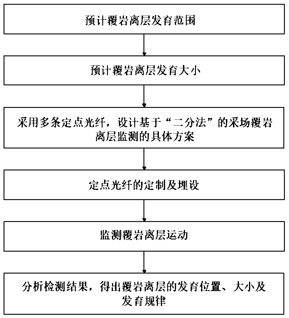
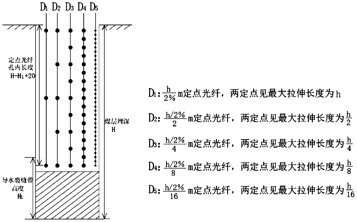
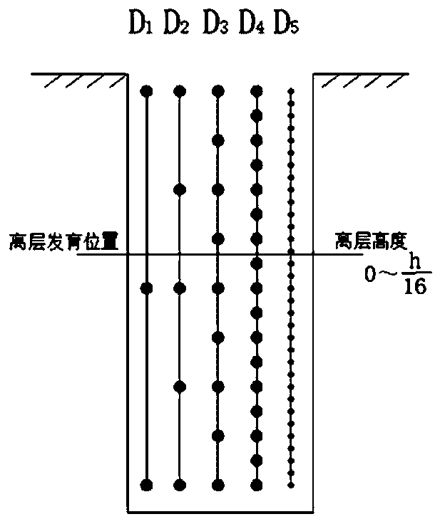
The invention discloses a stope overlying rock separation layer monitoring method based on optical fiber, and belongs to the field of soil environment monitoring. The stope overlying rock separation layer monitoring method based on the optical fiber comprises the steps that firstly, the development range of an overlying rock separation layer is predicted; secondly, the development size of the overlying rock separation layer is predicted; thirdly, five fixed point optical fibers are adopted, and the concrete schemes of stope overlying rock separation layer monitoring based on 'dichotomy' is designed; fourthly, customization and burying of the fixed point optical fiber are conducted; fifthly, movement of overlying rock separation layer is monitored; and sixthly, the inspecting result is analyzed, and the development position, size and regulation of the overlying rock separation layer are obtained. According to the stope overlying rock separation layer monitoring method based on the optical fiber, the stope overlying rock separation layer monitoring method is based on an optical fiber technology, the optical fiber is a sensing original copy and a transmission original copy, the tensile deformation of the separation layer can be monitored, compressed deformation of the separation layer can further be monitored, the expansion-closing-stabilizing development processes of the separation layer are researched advantageously, five fixed point optical fibers designed based on the'dichotomy' are adopted, the development position and volume of the overlying rock separation layer can beaccurately determined, slip casting and sinking-reduction of the separation layer are conducted advantageously, ground sinking is avoided, and the soil environment is protected.

Description

technical field [0001] The invention relates to the technical field of soil environment monitoring, in particular to an optical fiber-based monitoring method for overlying rock detachment layer in a stope. Background technique [0002] With the mining of the coal seam, the stress balance state of the rock mass around the goaf is broken, and the overlying strata undergo deformation movements such as collapse, fracture, and bending, and successively form caving zones, water-conducting crack zones, and bending subsidence from bottom to top. When the abscission space in the curved subsidence zone is closed, the overlying rock movement will develop to the surface, and the ground will collapse, which will bring huge losses to people's production, life, transportation, etc., and affect the ecological environment and sustainable economic development. Goaf subsidence changes the mechanical and chemical properties of the soil, destroys cultivated land and grassland, causes low-lying g...

Claims


Application Information

Patent Timeline
Patent Type & Authority Applications(China)
IPC IPC(8): G01N21/84G01N33/24
Inventor 魏久传牛会功谢道雷徐建国张秋生尹会永张伟杰
Owner SHANDONG UNIV OF SCI & TECH
Why Eureka
Try Eureka