Non-slip mat

A technology of anti-slip mat and mat body, applied in the field of floor mats, can solve the problems of poor anti-skid ability, poor anti-slip effect of floor mats, and inability to form negative pressure in the disc cavity, etc., to achieve enhanced anti-skid ability and flexible layout design , enhance the effect of anti-slip ability

Pending Publication Date: 2019-06-18
ZHEJIANG JIAJIE PLASTIC CO LTD
View PDF4 Cites 0 Cited by
  • Summary
  • Abstract
  • Description
  • Claims
  • Application Information

AI Technical Summary

Problems solved by technology

[0003] However, in actual use, the contact between the suction cup and the ground is not reliable, mainly because the bottom of most suction cups is directly combined with the pad body at a close distance, and the suction cup is easy to be stepped on the bottom and turned over, which cannot form a negative pressure in the disk cavity, so that There is no way to guarantee the existence of the adsorption force of the suction cup, so that the anti-slip effect of the floor mat is not good, especially the anti-slip ability is poor, and the drainage and hydrophobic function of the mat body is reduced. After scratching, it is not suitable to wash the dirty ones, and the cushioning of the foot feeling is lacking. comfort function

Method used


Image

  • Non-slip mat
  • Non-slip mat
  • Non-slip mat

Examples


Embodiment 1

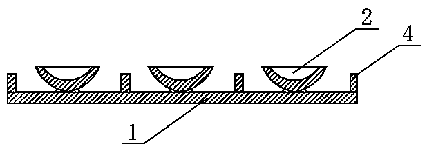
[0036] Embodiment 1: as figure 1 As shown, a non-slip pad includes a pad body 1, nine suction cups 2 are arranged on the lower surface of the pad body 1, and one hundred and twenty-one bosses 4 are also arranged on the lower surface of the pad body 1. The end face of the mouth of the sucker 2 is higher than the free end face of the boss 4, and the inner bottom of the sucker 2 is lower than the free end face of the boss 4.

Embodiment 2

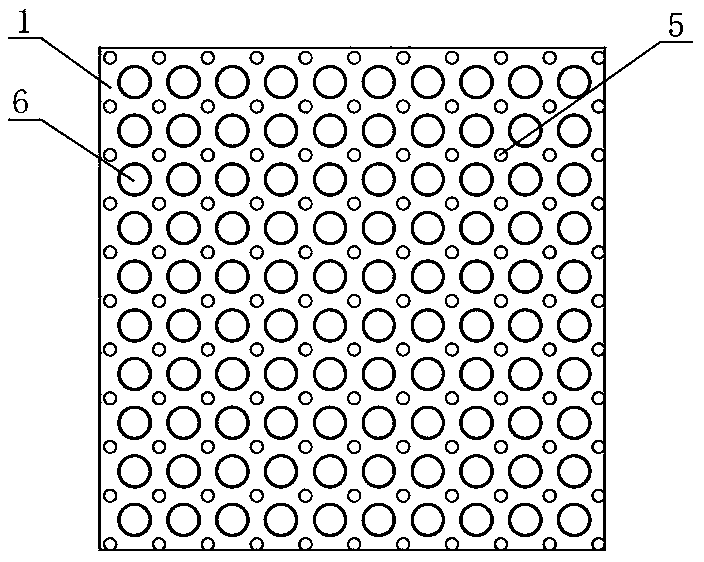
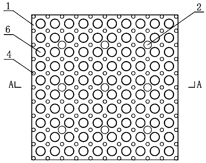
[0037] Embodiment 2: as figure 2 , image 3 and Figure 4 , a non-slip pad, comprising a pad body 1, nine suction cups 2 are arranged on the lower surface of the pad body 1, and one hundred and twenty-one bosses 4 are also arranged on the lower surface of the pad body 1.

[0038] Each suction cup is connected with the pad body 1 through a connecting shaft 3 . The opening end surface of the suction cup 2 is higher than the free end surface of the convex post 4, and the inner bottom of the suction cup 2 is lower than the free end surface of the convex post 4, that is, the length of the convex post 4 is less than the connecting shaft 3 plus the thickness of the inner bottom of the suction cup 2 and the thickness of the suction cup 2. The sum of the depth of the cavity and the length of the boss 4 are greater than the sum of the connecting shaft 3 and the wall thickness of the inner bottom of the suction cup 2 .

[0039] One hundred and twenty-one convex cakes 5 are arranged o...

Embodiment 3

[0040] Embodiment 3: The inner bottom of the suction cup 2 is provided with a settling tank 7 extending inward until it enters the pad body 1 .

[0041] All the other are with embodiment 1.


PUM


Abstract

The invention discloses a non-slip mat. The non-slip mat comprises a mat body and is characterized in that the lower surface of the mat body is provided with a plurality of suckers, the lower surfaceof the mat body is provided with a plurality of protruding columns, the opening end faces of the suckers are higher than the end faces of the free ends of the protruding columns, and the inner bottomsof the suckers are lower than the end faces of the free ends of the protruding columns. The non-slip mat has the advantages that the suckers and the protruding columns are combined, the suckers cannot be easily stepped to the floor and turned, sufficient sealing and constant negative pressure of the sucker cavities are guaranteed, the sucking force of the sucker to the floor is enhanced greatly,the slip preventing ability of the mat body is enhanced, and especially the lateral slip resistance of the mat body is enhanced.

Description

technical field [0001] The invention relates to the technical field of floor mats, in particular to an anti-slip mat. Background technique [0002] The floor mat is laid on the floor of the entrance, kitchen, dining room, bedroom, bathroom or swimming pool, etc., and is used to effectively scrape off mud and water at the entrance and keep the floor clean. Certainly its biggest effect is exactly anti-slip, especially in the bathroom, anti-slip function is particularly important, so the ground mat of prior art all adds suction cup on the lower surface, and suction cup can effectively absorb the ground mat to prevent sliding on the ground. [0003] However, in actual use, the contact between the suction cup and the ground is not reliable, mainly because the bottom of most suction cups are directly combined with the pad body at close range, and the suction cup is easy to be stepped on to the bottom and turned over, which cannot form a negative pressure in the disk cavity, so tha...

Claims


Application Information

Patent Timeline
Patent Type & Authority Applications(China)
IPC IPC(8): A47G27/02A47G27/04
Inventor 吴智芳
Owner ZHEJIANG JIAJIE PLASTIC CO LTD
Why Eureka
Try Eureka