
Medium and low speed magnetic levitation F-rail machining forming cutter and axial adjusting method of forming cutter

A processing and forming, maglev technology, applied in the direction of manufacturing tools, metal processing equipment, milling cutters, etc., to save time, ensure the processing accuracy requirements, reliable and effective processing accuracy requirements

Pending Publication Date: 2019-06-18
CHINA RAILWAY BAOJI BRIDGE GRP
View PDF0 Cites 2 Cited by
  • Summary
  • Abstract
  • Description
  • Claims
  • Application Information

AI Technical Summary

Problems solved by technology

1, 2, 3 sides ( image 3 ) requires three passes

Method used


Image

  • Medium and low speed magnetic levitation F-rail machining forming cutter and axial adjusting method of forming cutter
  • Medium and low speed magnetic levitation F-rail machining forming cutter and axial adjusting method of forming cutter
  • Medium and low speed magnetic levitation F-rail machining forming cutter and axial adjusting method of forming cutter

Examples


Embodiment 1

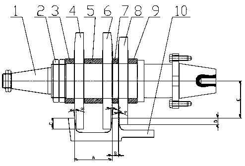
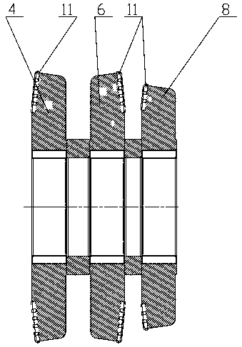
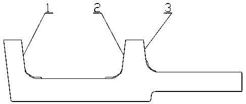
[0014] Embodiment 1: with reference to attached figure 1 —3. A medium-low speed maglev F-rail processing forming tool, including F-rail ( image 3 ), the first forming disc milling cutter 4, the second forming disc milling cutter 6 and the third forming disc milling cutter 8 are connected in series through the cutter shaft 1 and between the first forming disc milling cutter 4 and the second forming disc milling cutter 6 A first spacer 5 is placed, a second spacer 7 is placed between the second forming disc milling cutter 6 and the third forming disc milling cutter 8, and the positioning sleeve 9 is located on the cutter shaft 1 and is used for positioning the third forming disc milling cutter Cutter 8, compression sleeve 3 are enclosed within on the cutter shaft 1 and after the first forming disc milling cutter 4 is compressed, are positioned by the tightening round nut 2 that is screwed on the cutter shaft 1.

[0015] The outer surface of the first forming disc milling cutt...

Embodiment 2

[0022] Embodiment 2: On the basis of Embodiment 1, a method for axial adjustment of the forming cutter for medium and low-speed maglev F rail processing: adjust the first forming disc milling cutter 4 and the second forming disc milling cutter 6 through the positioning sleeve 9 and the axial position of the third forming disc milling cutter 8 on the tool bar, so that the cutter head processing surfaces of the first forming disc milling cutter 4, the second forming disc milling cutter 6 and the third forming disc milling cutter 8 are respectively in line with the processed The F rail surface forms a complete fit after machining.


PUM


Abstract

The invention relates to a medium and low speed magnetic levitation F-rail machining forming cutter which is used for machining the magnetic levitation F-rail surface by once and is high in machiningprecision. The medium and low speed magnetic levitation F-rail machining forming cutter comprises an F-rail; a first forming disc milling cutter, a second forming disc milling cutter and a third forming disc milling cutter are connected together through a cutter shaft in series, and a first spacer bush is arranged between the first forming disc milling cutter and the second forming disc milling cutter; and a second spacer bush is arranged between the second forming disc milling cutter and the third forming disc milling cutter, a positioning sleeve is located on the cutter shaft and is used forpositioning the third forming disc milling cutter, a pressing sleeve sleeves the cutter shaft and tightly presses the first forming disc milling cutter, and then the first forming disc milling cutteris positioned by a screwing round nut which is screwed on the cutter shaft. The forming cutter and the axial adjusting method have the advantages that firstly, the machining efficiency is greatly improved, the F-rail three-time milling forming design in the background technology is designed into one-time milling forming, so that a large amount of time is saved; and secondly, the machining shape,the size and the relative position requirement of the F-rail machining surface are completely ensured by virtue of the shape and the position relation of the three cutter discs, the error of the cutter setting during repeated machining is avoided, and the machining precision requirement is reliably and effectively ensured.

Description

technical field [0001] The invention relates to a medium-low speed maglev F-rail machining forming tool and an axial adjustment method for the forming tool, which is formed by one-time processing of the maglev F-rail surface and has high machining accuracy, and belongs to the field of manufacturing special-purpose processing tools for the F-rail. Background technique [0002] The F rail is the main functional part of the medium and low speed maglev track, and the rolled F-shaped steel needs to be machined to meet the functional requirements of the F rail. The cross-sectional shape and requirements of the F rail are as follows: image 3 As shown, it is used to process the 1, 2, and 3 sides of the F rail, such as image 3 shown. The existing processing method is to use an angled special rod milling cutter to respectively process the 1, 2, and 3 surfaces ( image 3 ) for processing, such as Figure 4 , Figure 5 , Image 6 shown. 1, 2, 3 sides ( image 3 ) requires three pa...

Claims


Application Information

Patent Timeline
IPC IPC(8): B23C5/12
Inventor 祁宝金王涛张琳吉敏廷牛均宽吴海宏郭江海邓宗生杨哲晨
Owner CHINA RAILWAY BAOJI BRIDGE GRP
Features
  • Generate Ideas
  • Intellectual Property
  • Life Sciences
  • Materials
  • Tech Scout
  • Unparalleled Data Quality
  • Higher Quality Content
  • 60% Fewer Hallucinations
Learn More