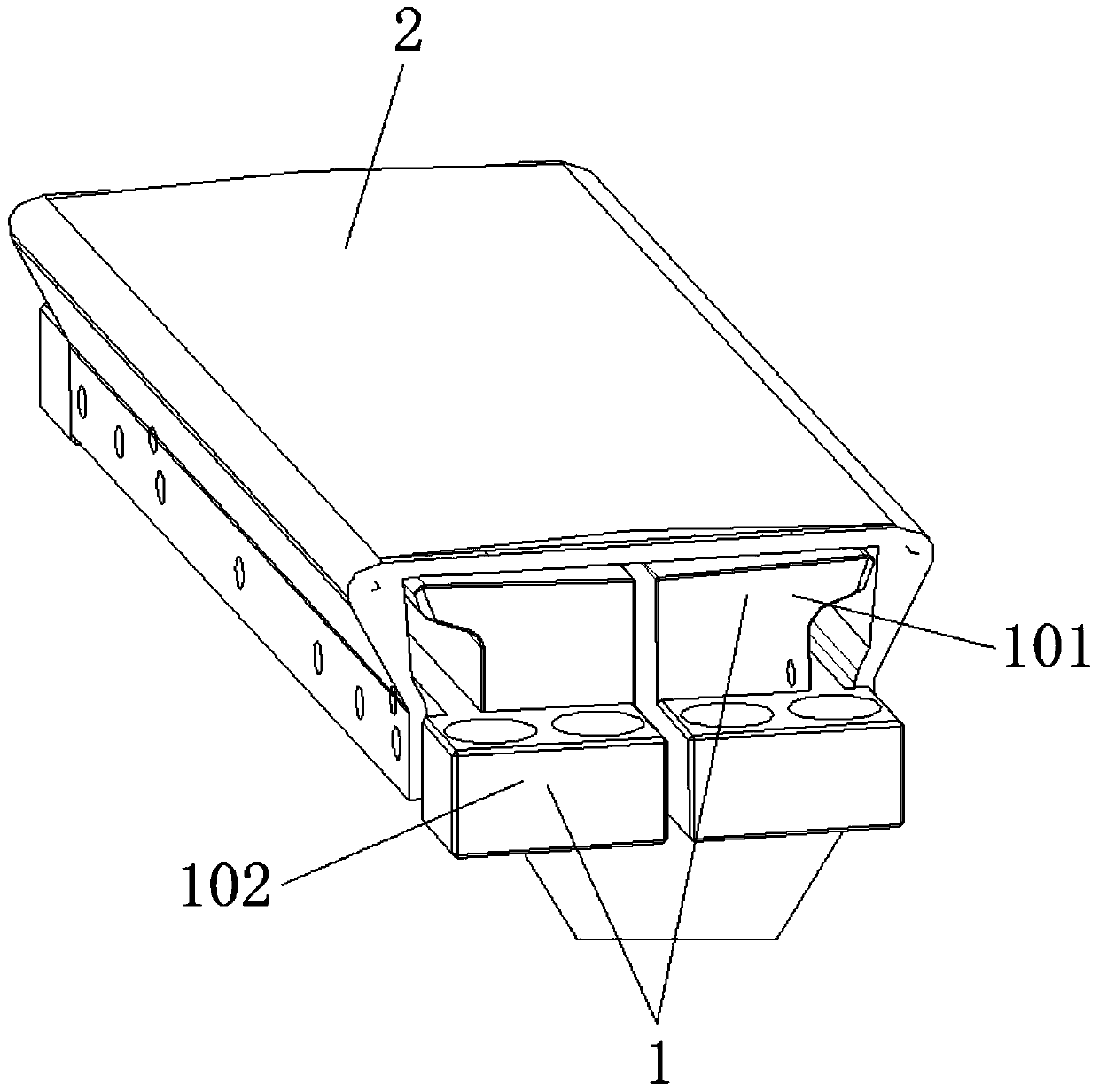
A pad bonding fixture
A technology for laminating fixtures and fixtures, applied in lamination auxiliary operations, chemical instruments and methods, lamination, etc., can solve problems such as not being able to meet general attachment requirements, and achieve diversified implementation methods and product lamination sizes Precise, contoured fit for accurate results
- Summary
- Abstract
- Description
- Claims
- Application Information
AI Technical Summary
Problems solved by technology
Method used
Image
Examples
Embodiment 1
[0016] see figure 1 , the present invention provides a technical solution: a PAD bonding jig, including a jig body 1 and a PAD profiling 2, the jig body 1 is mainly composed of a left jig 101 and a right jig 102, the left jig The surface of 101 and the right jig 102 are both downward convex arc surfaces, using horn structure, used for the precise attachment of PAD profiling 2, to achieve the effect of perfect fit with the product, the left jig 101 and the right jig 102 are installed on the jig On the adjustment mechanism, under the action of the jig adjustment mechanism, both the left jig 101 and the right jig 102 can be expanded and closed, eliminating the influence that the flatness is greater than the product in the process of attaching and pressing, so that the lamination size of the product is more accurate , no air bubbles and cracks, the distance parameter can be adjusted, and the size of the product attachment can be changed to make the profiling fit more accurate. The...
Embodiment 2
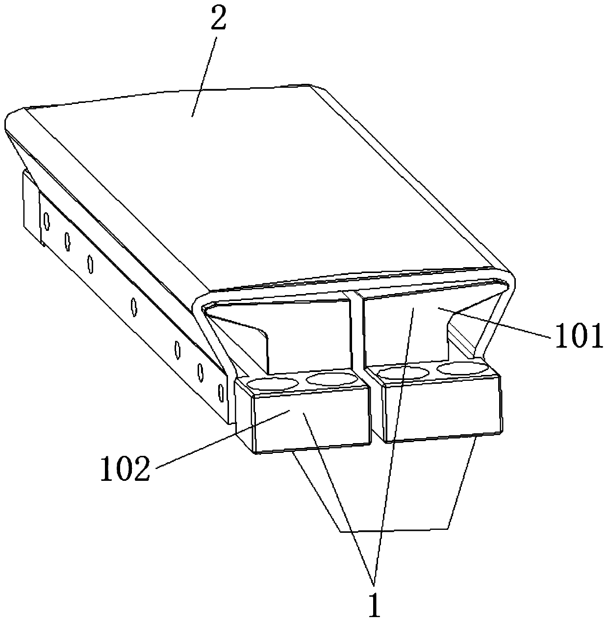
[0018] see figure 2 , the present invention provides a technical solution: a PAD bonding jig, including a jig body 1 and a PAD profiling 2, the jig body 1 is mainly composed of a left jig 101 and a right jig 102, the left jig The surface of 101 and the right jig 102 are both downward convex arc surfaces, using horn structure, used for the precise attachment of PAD profiling 2, to achieve the effect of perfect fit with the product, the left jig 101 and the right jig 102 are installed on the jig On the adjustment mechanism, under the action of the jig adjustment mechanism, both the left jig 101 and the right jig 102 can be expanded and closed, eliminating the influence that the flatness is greater than the product in the process of attaching and pressing, so that the lamination size of the product is more accurate , no air bubbles and cracks, the distance parameter can be adjusted, and the size of the product attachment can be changed to make the profiling fit more accurate. Th...
Embodiment 3
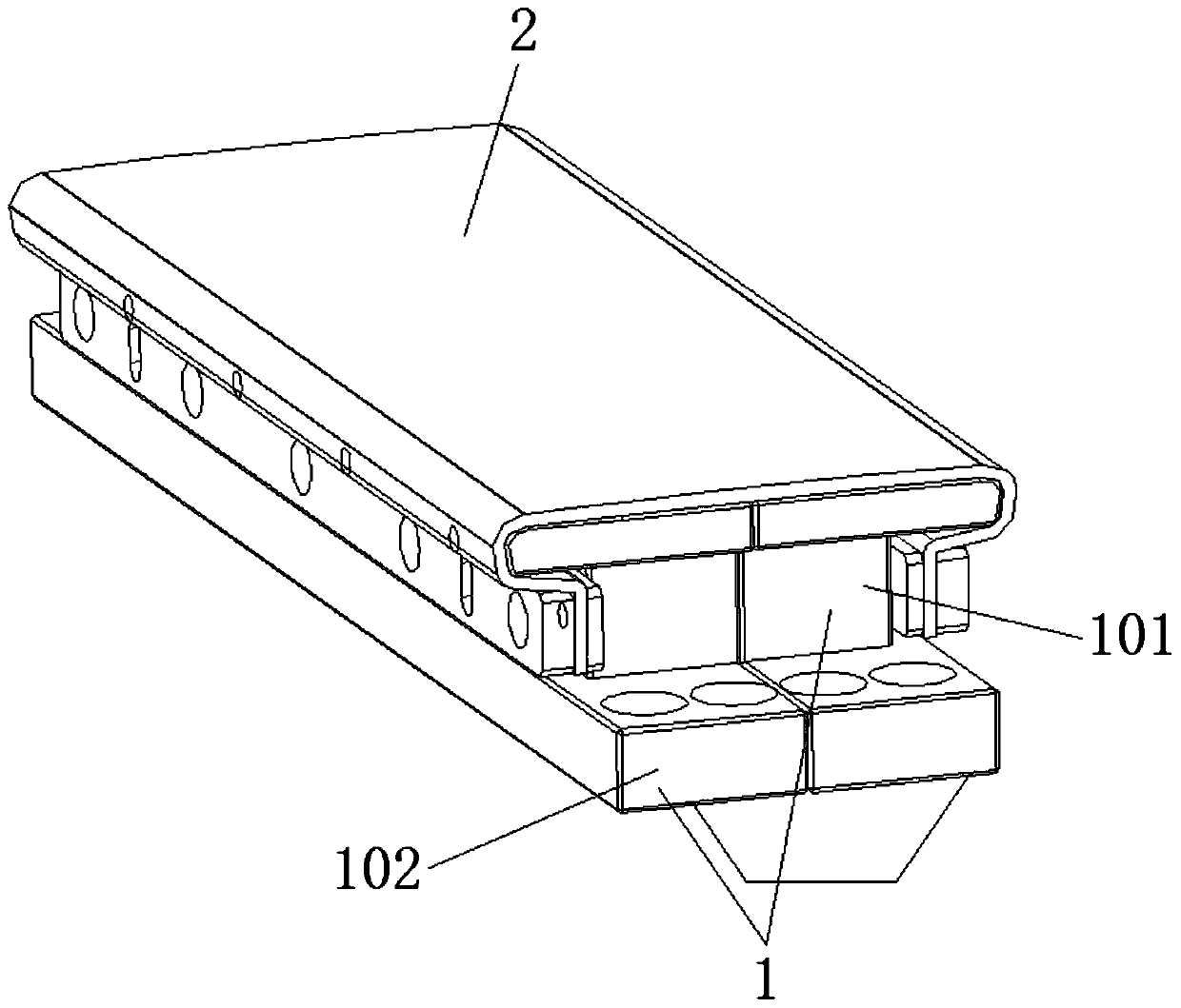
[0020] see image 3 , the present invention provides a technical solution: a PAD bonding jig, including a jig body 1 and a PAD profiling 2, the jig body 1 is mainly composed of a left jig 101 and a right jig 102, the left jig The surface of 101 and the right jig 102 are both flat, using the claw structure, which is used for the precise attachment of the PAD profiling 2 to achieve a perfect fit with the product. The left jig 101 and the right jig 102 are installed on the jig adjustment mechanism , under the action of the jig adjustment mechanism, both the left jig 101 and the right jig 102 can be expanded and closed, eliminating the influence of flatness greater than the product during the lamination process, so that the lamination size of the product is more precise and free of air bubbles and cracks, the distance parameters can be adjusted, and the product attachment size can be changed to make the profiling fit more accurate. The PAD profiling 2 is installed on the outside o...
PUM
 Abstract
Description
Claims
Application Information
 - R&D
- Intellectual Property
- Life Sciences
- Materials
- Tech Scout
- Unparalleled Data Quality
- Higher Quality Content
- 60% Fewer Hallucinations
Browse by: Latest US Patents, China's latest patents, Technical Efficacy Thesaurus, Application Domain, Technology Topic, Popular Technical Reports.
© 2025 PatSnap. All rights reserved.Legal|Privacy policy|Modern Slavery Act Transparency Statement|Sitemap|About US| Contact US: help@patsnap.com


