Hoisting equipment for bridge
A technology for hoisting equipment and bridges, applied to cranes, trolley cranes, hoisting equipment braking devices, etc. simple effect
- Summary
- Abstract
- Description
- Claims
- Application Information
AI Technical Summary
Problems solved by technology
Method used
Image

Examples
Embodiment 1
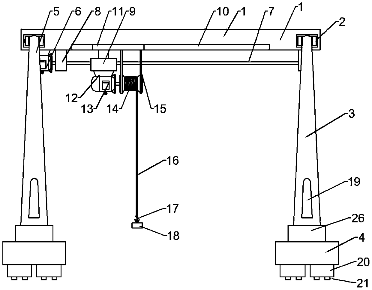
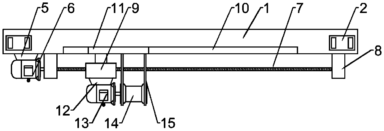
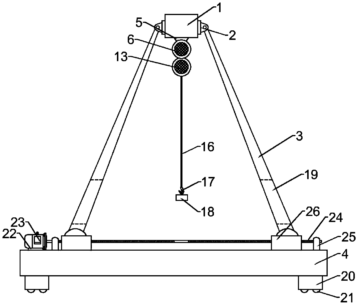
[0024] Example 1: Please refer to Figure 1-4 , a lifting device for a bridge, comprising an upper beam 1, four support beams 3 and a sliding base 4, both ends of the upper beam 1 are fixedly connected to the front and back symmetrically with a rotating connection seat 2, and the upper ends of the support beam 3 are respectively connected to the rotating connection seat 2 Rotationally connected, the left side below the upper crossbeam 1 is fixedly connected with the first motor base 5, the bottom of the first motor base 5 is fixedly connected with the first motor 6, and the output end of the first motor 6 is fixedly connected with the first transmission screw 7, so The outside of the first transmission screw 7 is screwed with an adjustment seat 9; the bottom of the upper beam 3 is provided with a guide chute 10, and the inside of the guide chute 10 is slidably connected with a guide slider 11, and the adjustment seat 9 and the guide slider 11 fixed connection between
[0025]...
Embodiment 2
[0038] Embodiment 2: This embodiment is a further improvement of the previous embodiment: in this embodiment, the first motor 6 is used to replace the first motor 6 to drive the mechanism for the left and right movement of the adjustment seat 9, and the telescopic end of the electric telescopic rod is fixedly connected to the adjustment seat 9 , The structure of the electric telescopic rod is simpler, the transmission efficiency is more direct, and it is also worth promoting.
[0039] The working principle of the present invention is: the present invention controls the rotation of the first motor 6 through the remote control device when in use, the rotation of the first motor 6 drives the first transmission screw 7 to rotate, and the rotation of the first transmission screw 7 can drive the adjustment seat 9 to move left and right, The direction of motion is controlled by controlling the rotation direction of the first motor 6, thereby realizing the left and right adjustment of ...
PUM
 Abstract
Description
Claims
Application Information
 - R&D
- Intellectual Property
- Life Sciences
- Materials
- Tech Scout
- Unparalleled Data Quality
- Higher Quality Content
- 60% Fewer Hallucinations
Browse by: Latest US Patents, China's latest patents, Technical Efficacy Thesaurus, Application Domain, Technology Topic, Popular Technical Reports.
© 2025 PatSnap. All rights reserved.Legal|Privacy policy|Modern Slavery Act Transparency Statement|Sitemap|About US| Contact US: help@patsnap.com