Luminous floor tile

A technology of floor tiles and light-transmitting resin, which is applied to semiconductor devices of light-emitting elements, light sources, lighting and heating equipment, etc., can solve the problems of short circuit, floor tile module replacement, slow installation progress, etc., to achieve uniform heat dissipation and alleviate impact force. Effect

Active Publication Date: 2019-06-18
NANTONG TIANCHENG OPTOELECTRONICS TECH CO LTD +2
View PDF8 Cites 11 Cited by
  • Summary
  • Abstract
  • Description
  • Claims
  • Application Information

AI Technical Summary

Problems solved by technology

When the above-mentioned floor tile modules are applied, the floor tile modules are generally directly poured into the concrete. Because the floor tile modules are frequently subjected to the impact of vehicles and pedestrians, the floor tile modules are easily damaged and difficult to replace, which increases the operating costs of the traffic management department. It is also not conducive to the long-term use of the floor tile module; and because the floor tile module can generate heat, the heat dissipation range poured in concrete is limited and the heat dissipation effect of concrete is poor, so it has the disadvantage of being difficult to dissipate heat; Too much water leads to problems such as short circuit of the line; the installation progress is relatively slow, and it is difficult to align, and problems such as offset are prone to occur during the installation process; there are difficulties in cable connection during installation, and once the cable has a problem, it is easy to cause the floor tile module to be damaged. Entire replacement, increasing management and operating costs for the transportation sector

Method used


Image

  • Luminous floor tile
  • Luminous floor tile
  • Luminous floor tile

Examples


Embodiment 1

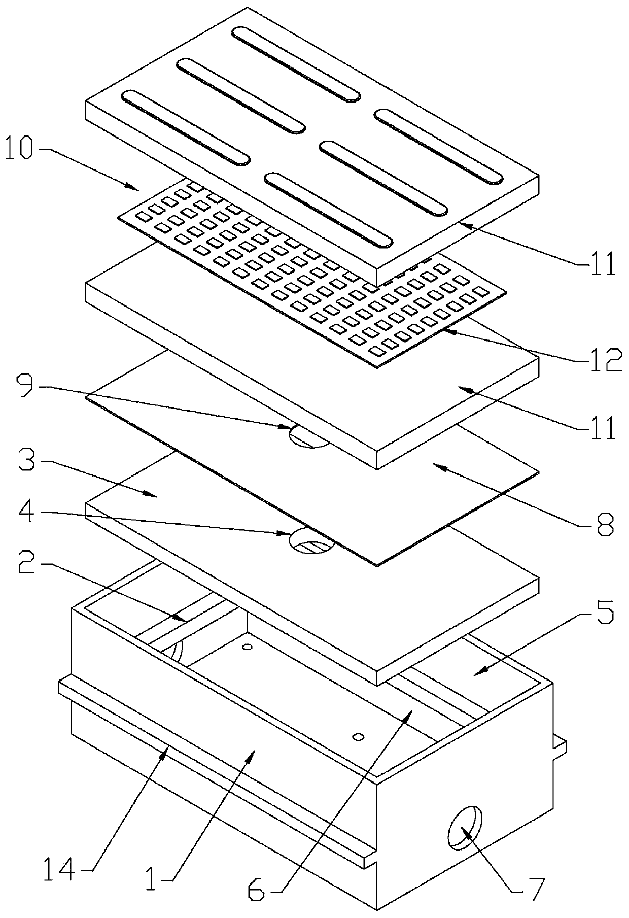
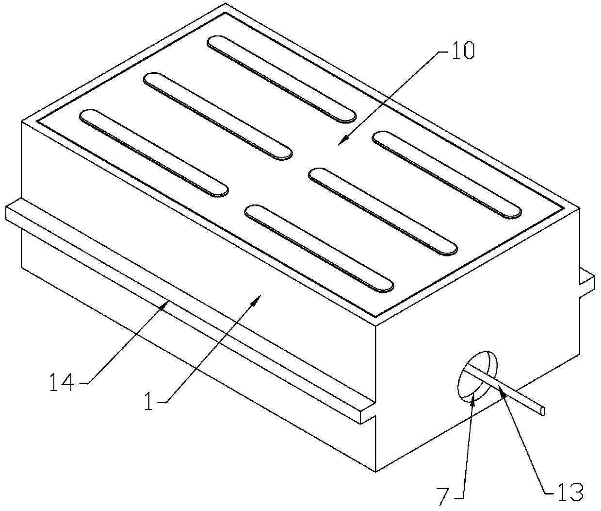
[0034] Such as Figure 1-2, as shown in 6-9: a kind of luminous floor tiles, including a mounting seat 1 and a floor tile module 10, the floor tile module 10 is composed of a light-transmitting resin block 11 and an LED light-emitting plate 12 packaged in the light-transmitting resin block 11, the light-transmitting The resin block 11 is made of resin material. The LED light-emitting board 12 is packaged inside the light-transmitting resin block 11, and the cable 13 of the LED light-emitting board 12 is led out through the light-transmitting resin block 11 downwards. The cable 13 is used for connecting External power supply and external intelligent controller; the mounting base 1 is a hollow body made of pressure-resistant material, and the inner cavity wall of the mounting base 1 is provided with a support boss 2 for supporting the pressure bearing plate 3. The plate 3 is provided with a pressure plate wire hole 4 for the cable 13 to pass through, and the pressure plate 3 div...

Embodiment 2

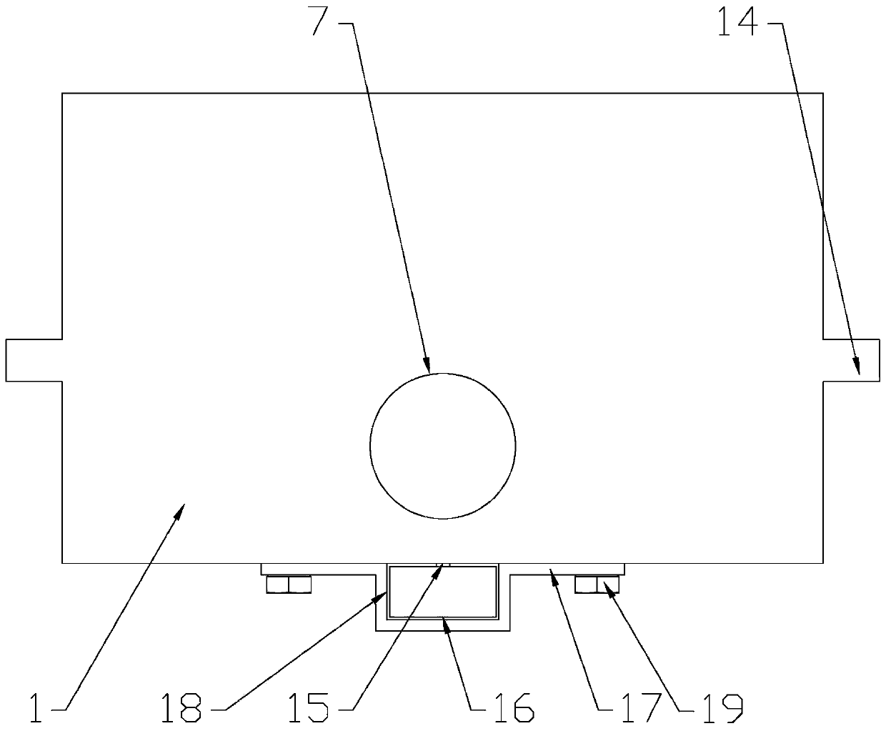
[0039] Such as image 3 , 5 -9 shows: on the basis of Embodiment 1, a permeable hole 15 is provided on the bottom plate of the mounting seat 1, and a drainage pipe 16 fixed on the mounting seat 1 is provided below the mounting seat 1 corresponding to the water permeable hole 15. The drain pipe 16 is a square steel pipe and the drain pipe 16 is provided with a water inlet corresponding to the permeable hole 2. The water outlet of the above drain pipe 16 is arranged at the seepage well; The bottom and the hoop 17 are fixed on the bottom of the mounting base 1 by hoop bolts 19 , the above hoop 17 is provided with a groove 18 for accommodating the drain pipe 16 and the upper edge of the groove 18 is flush with the bottom surface of the mounting base 1 .

[0040] Such as Figure 5-6 , 8-9: when multiple mounting bases 1 are arranged continuously, the drain pipe 16 can connect the multiple mounting bases 1 in series. Moreover, the serial connection of a plurality of mounting base...

Embodiment 3

[0043] Such as Figure 4-9 As shown: on the basis of Embodiment 1, angle steels 20 capable of fixing each mounting seat 1 are respectively provided at the outer walls on both sides of the bottom of each mounting seat 1, so that each mounting seat 1 can be positioned on the same straight line and set location. The angle steel 20 is arranged along the length direction of the installation base 1 and the angle steel 20 is fixed on the bottom plate of the installation base 1 by angle steel bolts 21 . The L-shaped angle steels 20 are parallel and symmetrically arranged on both sides of the mounting base 1 and partially wrap the long side walls and the bottom plate of the mounting base 1 . Furthermore, the serial connection of a plurality of mounting bases 1 can improve the stability of the floor tile module after the embedding, and prevent adverse situations such as deviation of the mounting bases 1 from occurring. The number of multiple mounting seats 1 arranged in the same direc...


PUM


Abstract

The invention discloses a luminous floor tile. The luminous floor tile comprises an installing base (1) and a floor tile module (10). The installing base (1) is a cavity body made of a pressure-resistant material. A cavity wall of the installing base (1) is provided with a support convex platform (2) for supporting a bearing plate (3). The bearing plate (3) is provided with a bearing plate cable hole (4) through which a cable (130) passes, and a cavity of the installing base (1) is separated into an upper floor tile module installing groove (5) and a lower functional cavity (6) by the bearingplate (3). A side wall of the installing base (1) corresponding to the functional cavity (6) is provided with a cable passing hole (7). The cable passing hole (7) is used for, after enabling the cable(13) connected with the floor tile module (10) to be drawn out from the bottom of the floor tile module (10), enabling the cable (13) to successively pass through the bearing plate cable hole (4) andthe cable passing hole (7) and to be outwards stretched out. The luminous floor tile is capable of protecting the floor tile module, improving installing efficiency, and improving stability and electric safety degree after the floor tile module is buried.

Description

technical field [0001] The present invention relates to the technical field of transportation facilities, in particular to a device capable of protecting floor tile modules (including intelligent floor tile modules), draining water accumulated in the area of ​​floor tile modules in time, improving the installation efficiency of floor tile modules, and improving the efficiency of floor tile modules. Luminous floor tiles that are stable after the module is buried. Background technique [0002] The zebra crossing is the life safety line of pedestrians, but today, with the increasingly prominent contradiction between people and vehicles, traffic accidents on the zebra crossing are common, and this "safety line" has become unsafe. On the one hand, the safety of pedestrians crossing the street is ignored, on the other hand, drivers lack the awareness of giving way to pedestrians. For some drivers who maliciously run red lights and zebra crossings, administrative actions such as fi...

Claims


Application Information

Patent Timeline
Patent Type & Authority Applications(China)
IPC IPC(8): E01C5/04E01C17/00E01F9/50
CPCE01C5/04E01C17/00E01F9/50E01C15/00E01C2201/16E01C2201/10F21W2111/023F21Y2115/10
Inventor 顾金刚沈标徐海黎
Owner NANTONG TIANCHENG OPTOELECTRONICS TECH CO LTD
Why Eureka
Try Eureka