Supercharge Your Innovation With Domain-Expert AI Agents!

Device for controlling monitor to move periodically on a support

A technology for controlling monitors and brackets, applied in the direction of machines/supports, supporting machines, mechanical equipment, etc., can solve problems such as high manufacturing costs, achieve the effect of ensuring working hours and improving the quality of work and life

Pending Publication Date: 2019-06-18
胡安双
View PDF3 Cites 0 Cited by
  • Summary
  • Abstract
  • Description
  • Claims
  • Application Information

AI Technical Summary

Problems solved by technology

However, this technology has also entered into a misunderstanding. Firstly, the operator does not need to stare at the screen all the time; secondly, the moving screen will cause operator misoperation and lead to unpredictable consequences; thirdly, it has three driving motion mechanisms and non-standard design , will result in high manufacturing costs

Method used


Image

  • Device for controlling monitor to move periodically on a support
  • Device for controlling monitor to move periodically on a support
  • Device for controlling monitor to move periodically on a support

Examples


Embodiment 1

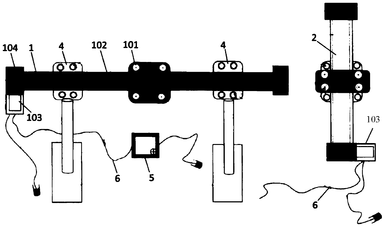
[0042] Such as figure 1 As shown, this embodiment includes: a horizontally-mounted linear slider guide rail mechanism 1, a longitudinally-mounted linear slider guide rail mechanism 2, a display card board 3, two sets of upright mechanisms 4, and a controller 5. The slider guide rail mechanism 1 and the longitudinally arranged linear slider guide rail mechanism 2 are orthogonally connected, the display card 3 is arranged on the longitudinal linear slider guide rail mechanism 2, and the controller 5 is connected with the drive motors on the linear slider guide rail mechanisms 1 and 2 103 is connected and transmits control signals to realize the timing movement of the display card 3.

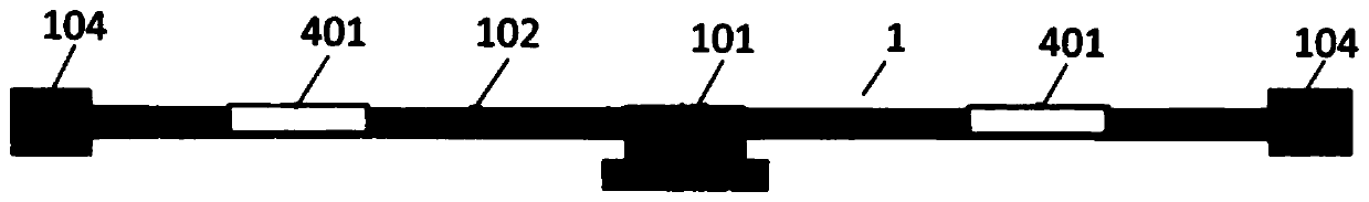
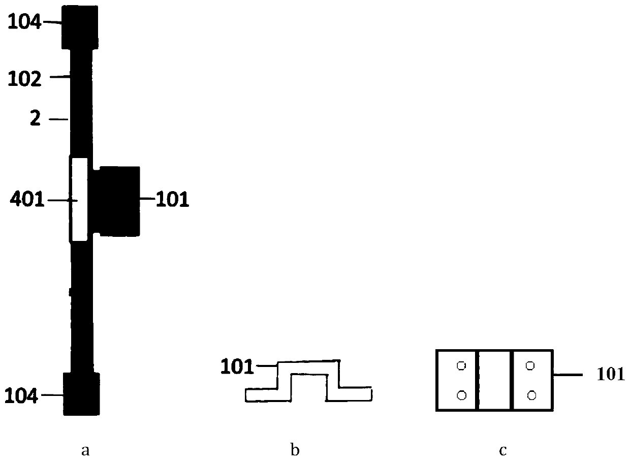
[0043] The linear slider guide rail mechanisms 1 and 2 include: a slider 101, a guide rail 102, a driving motor 103, and a baffle 104, wherein the slider 101 is movably arranged on the guide rail 102, and the driving motor 103 is fixedly arranged on the guide rail 102, The baffle 104 is arranged at bo...

Embodiment 2

[0056] Such as Figure 7 As shown, compared with Embodiment 1, this embodiment includes: a horizontally-positioned linear slider guide rail mechanism 1, a display card board 3, two sets of upright mechanisms 4 and a controller 5, wherein: the display card board 3 is arranged in the horizontal direction On the lateral linear slider guide mechanism 1, two sets of column mechanisms 4 are connected with the lateral linear slider guide mechanism 1 by bolts, and the controller 5 is connected with the drive motor 103 of the lateral linear slider guide mechanism 1 And transmit control signals to realize the timing movement of the display card board 3.

[0057] Compared with Embodiment 1, the exercise mode of this embodiment is horizontal exercise, including: preset main position, preset left auxiliary position, and preset right auxiliary position.

Embodiment 3

[0059] Such as Figure 8 As shown, compared with Embodiment 1, this embodiment includes: a longitudinally arranged linear slider guide rail mechanism 2, a display card board 3, a column mechanism 4 and a controller 5, wherein: the display card board 3 is set on the longitudinal linear slider On the guide rail mechanism 2, the column mechanism 4 is connected to the bottom end of the longitudinal linear slider guide mechanism 2, and the controller 5 is connected to the drive motor 103 of the longitudinal linear slider guide mechanism 2 and transmits control signals to realize the timing movement of the display card board 3.

[0060] Compared with Embodiment 1, the movement mode of this embodiment is vertical movement, which includes: preset main position, preset upper auxiliary position and preset lower auxiliary position.


PUM


Abstract

The invention provides a device for controlling a monitor to move periodically on a support. The device for controlling the monitor to move periodically on the support comprises one or more sets of linear sliding block guide rail mechanisms and a monitor clamping plate and a controller which are connected with the linear sliding block guide rail mechanisms respectively. The controller is connectedwith the linear sliding block guide rail mechanism, and control signals are transmitted by the controller so that different movement modes of the monitor clamping plate are achieved. One set of linear sliding block guide rail mechanism is in one-way connection with the monitor clamping plate in a horizontal, perpendicular or inclined manner, or two sets of linear sliding block guide rail mechanisms are in orthogonal connection and connected with the monitor clamping plate so that the monitor clamping plate can have movement choices of multiple directions simultaneously. According to the device for controlling the monitor to move periodically on the support, the periodical movement time and movement mode of the monitor clamping plate can be set autonomously by an user; and when an electricmonitor is used by the user to work or recreate, periodic passive movement can be done by the cervical spine, and thus damage to the cervical spine caused by long-time immobility is effectively prevented.

Description

Technical field [0001] The invention relates to a technology in the field of display stands, in particular to a device for controlling the timing movement of a display on the stand. Background technique [0002] Electronic equipment is an indispensable tool in human work and life today. While they provide convenience, they also pose a threat to human health. Staring at the display screen in a fixed posture for a long time for work or entertainment has caused problems in the cervical spine of many people, which in turn affects the blood supply to the brain and causes diseases such as hypertension. How to ensure people's normal work and entertainment without affecting the health of the cervical spine is an urgent problem to be solved. [0003] After searching the prior art, it is found that the invention patent with application number 201710256104.2 discloses a self-moving screen frame for preventing cervical spondylosis, which can make the screen on the frame follow the rotation of...

Claims


Application Information

Patent Timeline
IPC IPC(8): F16M11/04F16M11/18
Inventor 胡安双
Owner 胡安双
Features
  • R&D
  • Intellectual Property
  • Life Sciences
  • Materials
  • Tech Scout
  • Unparalleled Data Quality
  • Higher Quality Content
  • 60% Fewer Hallucinations
Learn More