Radio receiver and intermediate frequency signal generation method

A radio receiver and intermediate frequency signal technology, applied in the direction of electrical components, switched capacitor networks, frequency demodulator layout, etc., to prevent the reception performance from being degraded

Active Publication Date: 2019-06-18
RENESAS ELECTRONICS CORP
View PDF4 Cites 2 Cited by
  • Summary
  • Abstract
  • Description
  • Claims
  • Application Information

AI Technical Summary

Problems solved by technology

The BPF (Band Pass Filter) passes only signals in a predetermined frequency band of the IF signal o...

Method used


Image

  • Radio receiver and intermediate frequency signal generation method
  • Radio receiver and intermediate frequency signal generation method
  • Radio receiver and intermediate frequency signal generation method

Examples


no. 1 example

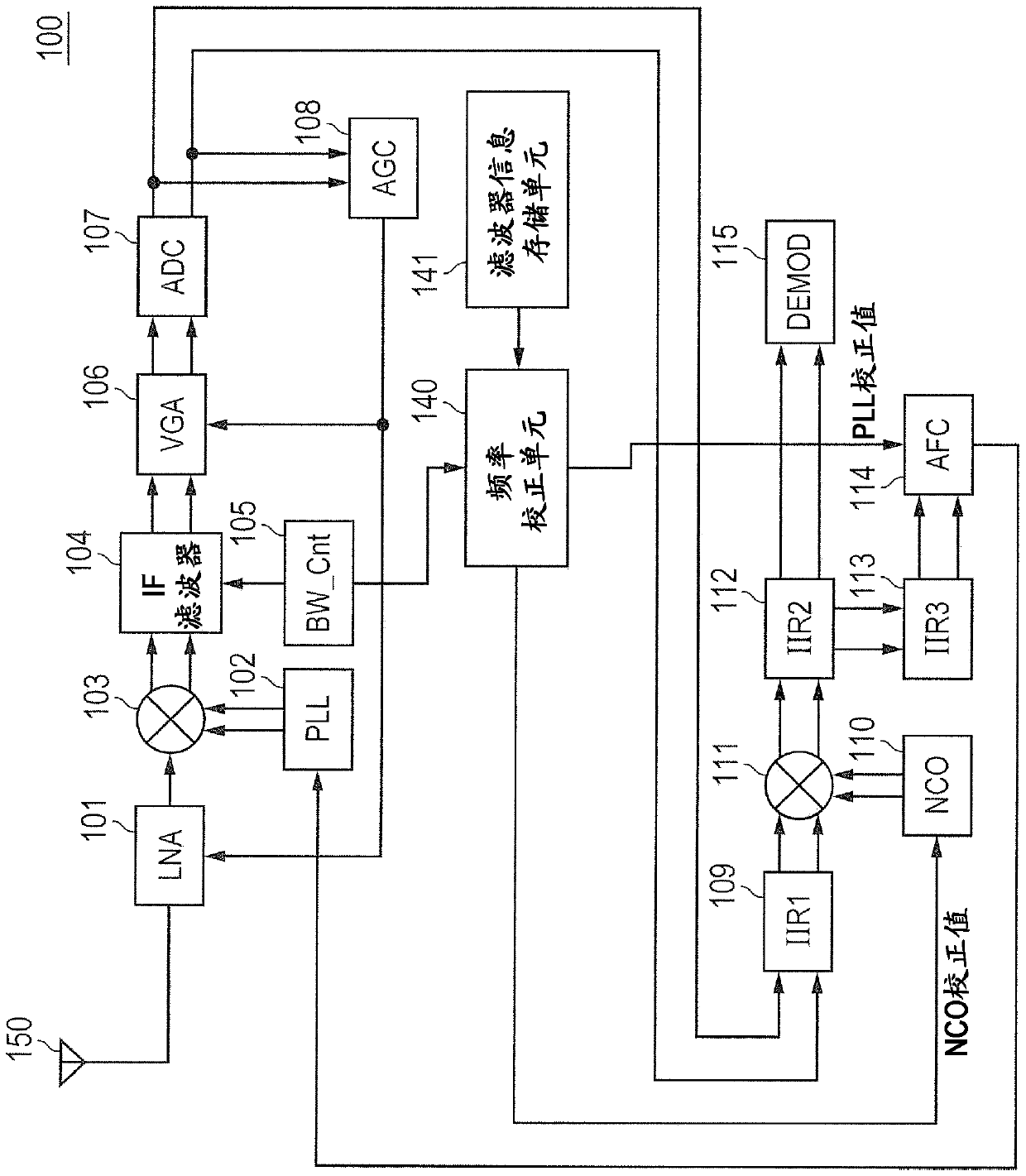
[0037] figure 1 A radio receiver according to a first embodiment is shown. The radio receiver 100 includes an LNA 101, a PLL 102, a mixer 103, an IF filter 104, a band control unit 105, a VGA 106, an AD converter 107, an AGC unit 108, an IIR filter 109, an NCO 110, a mixer 111, IIR filter 112 , IIR filter 113 , AFC unit 114 , demodulator 115 , frequency correction unit 140 and filter information storage unit 141 . In the configuration of the radio receiver 100 according to this embodiment, a frequency correction unit 140 and a filter information storage unit 141 are added to Figure 8 Corresponding components of the radio receiver 500 used for the study are shown.

[0038] For example, the antenna 150 receives radio frequency signals (RF signals) in the SubGHz frequency band. LNA 101 amplifies RF signals. PLL102 configures a local oscillator with variable oscillation frequency. The PLL 102 outputs a local oscillation signal to the mixer 103 . The mixer 103 configures a ...

no. 2 example

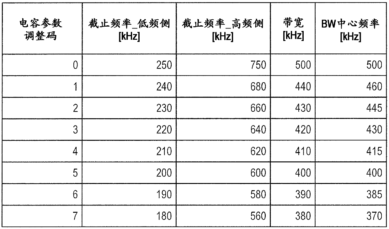
[0076] A second embodiment will be described below. The configuration of the radio receiver according to this embodiment is the same as figure 1 The configuration of the shown radio receiver 100 according to the first embodiment is the same. In the first embodiment, when the pass characteristic of the IF filter 104 is changed from the pass characteristic of the wide band to the pass characteristic of the narrow band, the frequency correcting unit 140 is based on the center frequency of the pass band before changing and the center frequency of the pass band after changing The difference between the oscillation frequency of the PLL 102 and the oscillation frequency of the NCO 110 is corrected. In this embodiment, further, the frequency correction unit 140 refers to the filter information storage unit 141 to obtain the center frequency of the passband of the wideband pass characteristic, and corrects the oscillation frequency of the PLL 102 and the oscillation frequency of the ...


PUM


Abstract

The disclosure relates to a radio receiver and an intermediate frequency signal generation method, and specifically relates to an IF filter that band-limits an intermediate frequency signal outputtedfrom a mixer. An AFC unit controls the oscillation frequency of a PLL so that the frequency of the intermediate frequency signal is a predetermined frequency. When the AFC unit controls the oscillation frequency of the PLL, a band control unit controls the passing characteristic of the IF filter to the passing characteristic of a wide band, and after the completion of the control, controls the passing characteristic of the IF filter to the passing characteristic of a narrow band. A frequency correction unit refers to a filter information storage unit, and corrects the oscillation frequency controlled by the AFC unit according to the difference between the center frequency of the passband of the passing characteristic of the wide band and the center frequency of the passband of the passingcharacteristic of the narrow band.

Description

[0001] Cross References to Related Applications [0002] The disclosure of Japanese Patent Application No. 2017-236395 filed on December 8, 2017 including specification, drawings and abstract is incorporated herein by reference. technical field [0003] The invention relates to a radio receiver and a method for generating an intermediate frequency signal. For example, the present invention relates to a radio receiver that converts a radio frequency signal into an intermediate frequency signal and receives the intermediate frequency signal, and an intermediate frequency signal generation method of such a radio receiver. Background technique [0004] Japanese Unexamined Patent Application Publication No. 2007-158780 (Patent Document 1) discloses a passband limiting device used in an FSK (Frequency Shift Keying) receiving apparatus. In the FSK receiving apparatus, a mixer mixes an RF (Radio Frequency) signal input through an antenna with a local oscillation signal, and genera...

Claims


Application Information

Patent Timeline
IPC IPC(8): H04B1/16
CPCH04B1/16H03D3/004H03D3/007H03D7/166H03H19/004H04B1/0007H04B1/1036H04B1/30H04B1/406
Inventor 内藤涉和泉宪佳木嶋和弘
Owner RENESAS ELECTRONICS CORP
Why Eureka
Try Eureka