Combined recreational vehicle seat connecting device and use method thereof

A connecting device and amusement vehicle technology, applied in entertainment devices, entertainment, etc., can solve the problems of passenger injury, shorten the space of front seats and rear seats, etc., and achieve the effect of reducing inertial impact

Active Publication Date: 2019-06-21
叶冰冰
View PDF1 Cites 2 Cited by
  • Summary
  • Abstract
  • Description
  • Claims
  • Application Information

AI Technical Summary

Problems solved by technology

[0002] Among the many amusement projects, recreational vehicles are the most common and one of people's favorite amusement projects. Since the number of tourists in amusement places will vary in different time periods, many recreational vehicle projects will adjust the recreational vehicles according to the number of tourists. The number of seats, in order to facilitate the adjustment of the seats, the seats are usually designed as a detachable structure, such as: an amusement seat connecting frame disclosed in the application number 201511010289.6, which passes the upper limit frame and the lower limit frame Squeeze the upper rack and the lower rack so that the teeth of the upper rack and the lower rack engage with each other, thereby connecting the upper rack and the lower rack, and aligning the two seats through the upper rack and the lower rack. However, with this connection structure, when the front and rear seats are connected, if the amusement vehicle suddenly stops or decelerates, the rear seat will drive the passengers to approach the front seat under the action of inertia, shortening the front seat and the rear seat. The space of the seat makes the passengers injured, in view of this, we propose a connection device for a combined recreational vehicle seat and its use method

Method used


Image

  • Combined recreational vehicle seat connecting device and use method thereof
  • Combined recreational vehicle seat connecting device and use method thereof
  • Combined recreational vehicle seat connecting device and use method thereof

Examples


Embodiment Construction

[0025] The following will clearly and completely describe the technical solutions in the embodiments of the present invention with reference to the accompanying drawings in the embodiments of the present invention. Obviously, the described embodiments are only some, not all, embodiments of the present invention. Based on the embodiments of the present invention, all other embodiments obtained by persons of ordinary skill in the art without creative efforts fall within the protection scope of the present invention.

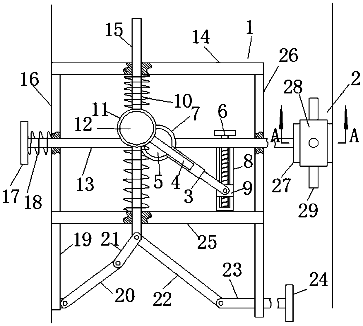
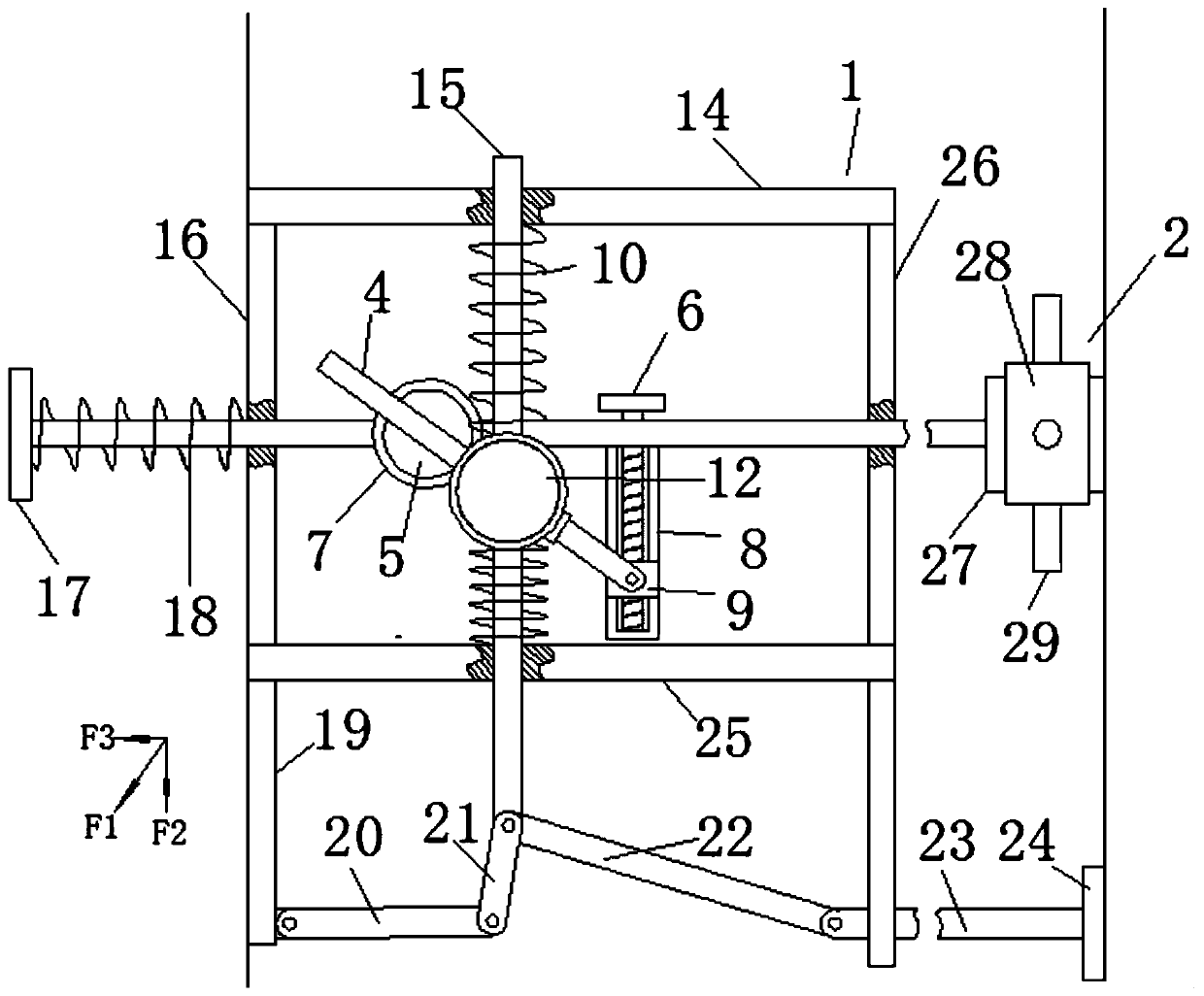
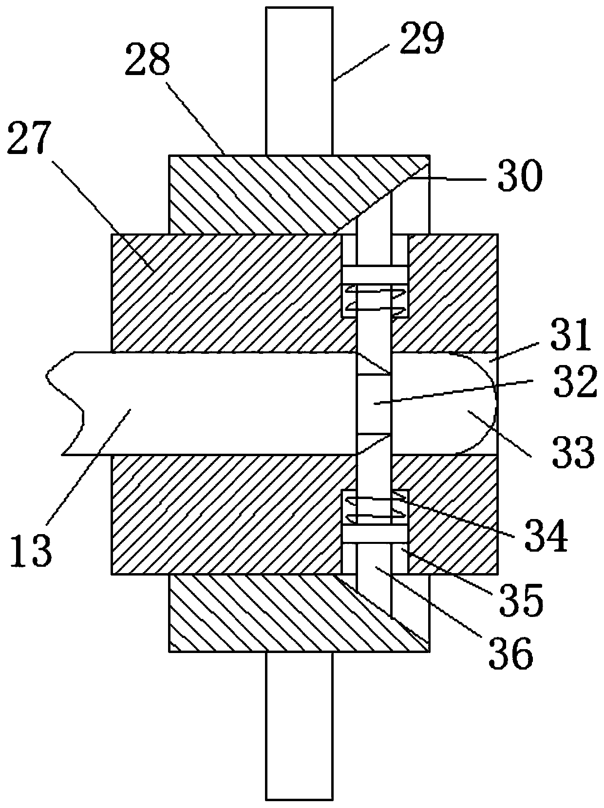
[0026] see Figure 1-6 , the present invention provides a technical solution: a combined recreational vehicle seat connection device and its use method, including a frame 1 fixed at the rear end of the front seat and a locking mechanism 2 fixed at the front end of the rear seat, the frame 1 It is a square frame structure composed of frame one 14, frame two 16, frame three 25 and frame four 26. A pull rod 13 is slidably inserted on frame two 16 and frame four 26, an...


PUM


Abstract

The invention relates to the field of recreation facilities, in particular to a combined recreational vehicle seat connecting device and a use method thereof. The combined recreational vehicle seat connecting device comprises a framework fixed at the back end of a front seat and a locking mechanism fixed at the front end of a back seat, wherein the framework is of a square frame structure consisting of a first side frame, a second side frame, a third side frame and a fourth side frame; a pull rod is glidingly inserted and connected onto the second side frame and the fourth side frame; one endof the pull rod can be connected with the locking mechanism, so that the back seat is connected onto the tail part of the front seat; an adjustable thrust mechanism is arranged on the pull rod; a polygon rod is glidingly inserted and connected onto the first side frame and the third side frame; a buffer mechanism is arranged on the polygon rod; the polygon rod is connected with the thrust mechanism; a tail section protection mechanism is arranged on the framework; the polygon rod is connected with the tail section protection mechanism. The combined recreational vehicle seat connecting device and the use method thereof have the advantages that the inertia impact of the front and back seats can be reduced; passengers are protected from impact injury; the buffer effect between the front and back seats can be regulated according to people with different bearing abilities.

Description

technical field [0001] The invention relates to the field of amusement facilities, in particular to a connecting device for a combined amusement vehicle seat and a method for using the same. Background technique [0002] Among the many amusement projects, recreational vehicles are the most common and one of people's favorite amusement projects. Since the number of tourists in amusement places will vary in different time periods, many recreational vehicle projects will adjust the recreational vehicles according to the number of tourists. The number of seats, in order to facilitate the adjustment of the seats, the seats are usually designed as a detachable structure, such as: an amusement seat connecting frame disclosed in the application number 201511010289.6, which passes the upper limit frame and the lower limit frame Squeeze the upper rack and the lower rack so that the teeth of the upper rack and the lower rack engage with each other, thereby connecting the upper rack and...

Claims


Application Information

Patent Timeline
Patent Type & Authority Applications(China)
IPC IPC(8): A63G31/00
Inventor 叶冰冰
Owner 叶冰冰
Why Eureka
Try Eureka