Separation sieve for water conservancy construction slurry conveying device

A technology of construction mud and conveying device, applied in the field of separation screen, can solve the problem of easy jamming of impurities in the chute, and achieve the effect of reducing the probability of being unusable and avoiding the unusable.

Active Publication Date: 2019-06-21
高会林
View PDF2 Cites 2 Cited by
  • Summary
  • Abstract
  • Description
  • Claims
  • Application Information

AI Technical Summary

Problems solved by technology

[0005] The present invention provides a separating screen used for the mud conveying device of water conservancy construction, which solves the problem in the prior art that impurities are easily stuck in the chute because the chute is set on the inner wall of the sieve

Method used


Image

  • Separation sieve for water conservancy construction slurry conveying device
  • Separation sieve for water conservancy construction slurry conveying device
  • Separation sieve for water conservancy construction slurry conveying device

Examples


Embodiment 1

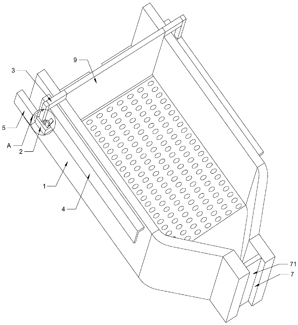
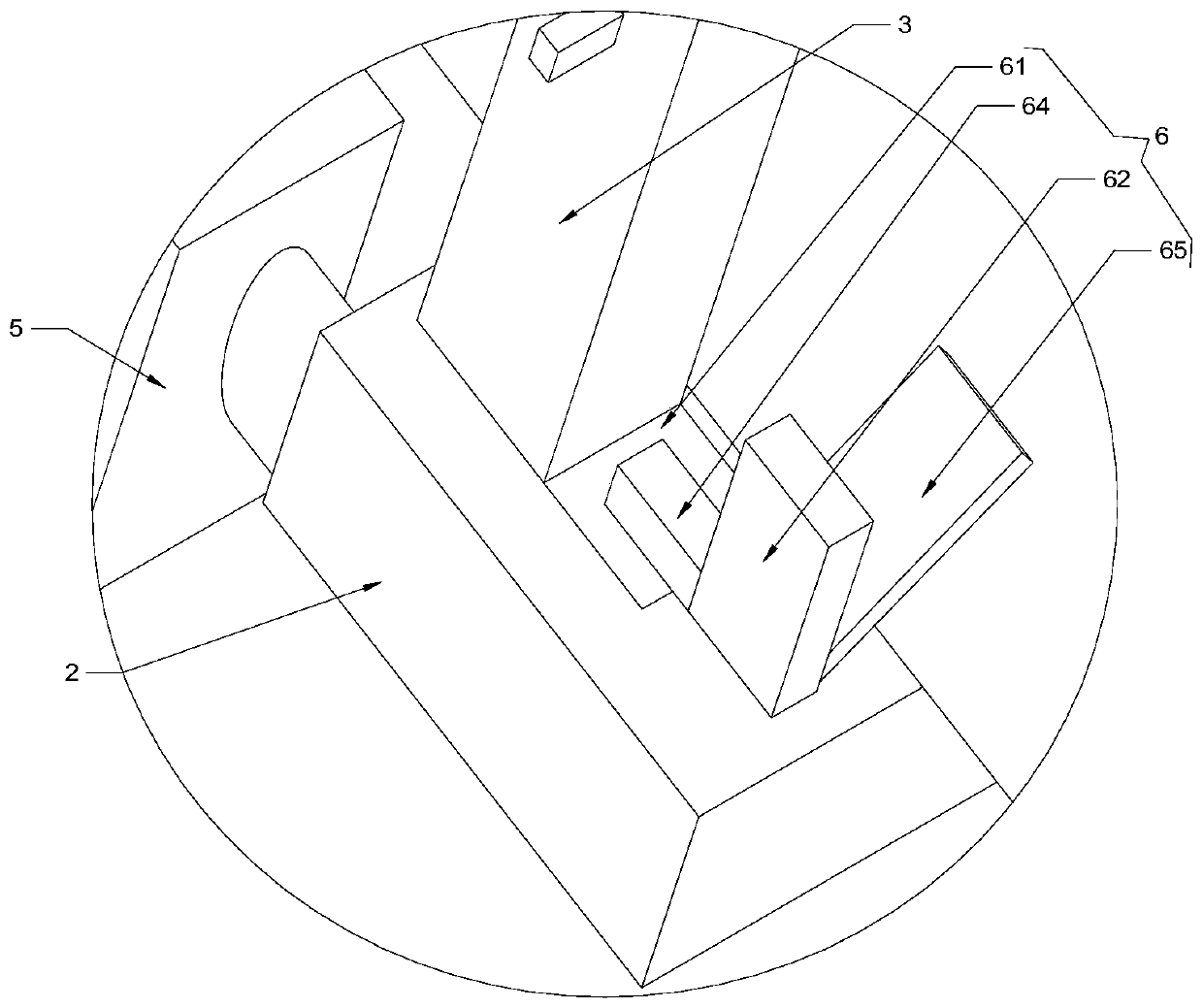
[0020] like Figure 1 to Figure 3 As shown, the present invention proposes a separation sieve for a hydraulic construction mud delivery device, comprising: a sieve body 1, where the high end of the sieve body 1 is located higher than the low end of the sieve body 1, and the high end of the sieve body 1 is used for inputting Separation of materials; two sliders 2, the outer walls of both sides of the sieve body 1 are recessed to form two chutes, and a slider 2 is installed in each chute, and the slider 2 is used to move between the high end of the sieve body 1 and the low end of the sieve body 1 Move; two covers 4, two covers 4 are installed on the outer walls on both sides of the screen body 1, each cover 4 is used to cover the joint between the slider 2 and the chute; two sliding rods 3, each slider 2 are connected to one end of a sliding rod 3; cleaning brush 9, the other end of each sliding rod 3 is fixed to the cleaning brush 9, the cleaning brush 9 is located in the sieve...

Embodiment 2

[0026] The difference between this embodiment and embodiment 1 is: on the basis of embodiment 1, the structure of the sieve body 1 is changed, and other structures remain unchanged.

[0027] like figure 1 , Figure 4 as well as Figure 5 As shown, the screen body 1 is equipped with an opening and closing assembly 7, and the opening and closing assembly 7 is used to open and close the bottom of the screen body 1. After the dumper of the transfer vehicle is filled with granular stones, another empty transfer vehicle needs to be replaced. If there are still granular stones discharged from the sieve body 1 at this time, the entire work site will be messy. Therefore, it is necessary to install an opening and closing assembly 7 to avoid the above phenomenon. When the transfer vehicle is aligned with the bottom of the sieve body 1, the opening and closing assembly 7 opens the bottom of the sieve body 1; when the transfer vehicle is away from the bottom of the sieve body 1, the open...


PUM


Abstract

The invention provides a separation sieve for a water conservancy construction slurry conveying device, which comprises a sieve body, two slide blocks, two cover bodies, two slide rods, a cleaning brush and a driving mechanism, wherein a sieve body high end is higher than a sieve body low end; the sieve body high end is used for conveying a material to be separated; outer walls on the two sides ofthe sieve body are indented to form two slide grooves; each slide block is mounted in each slide groove; the slide blocks move between the sieve body high end and the sieve body low end; the two cover bodies are mounted on the outer walls on the two sides of the sieve body; each cover body is used for covering a connecting part of each slide block and each slide groove; each slide block is connected to one end of each slide rod; the other end of each slide rod is fixed to the cleaning brush; the cleaning brush is located in the sieve body and used for sweeping an inner wall of the sieve body;and the driving mechanism is connected with the slide blocks and used for driving the slide blocks to slide in the slide grooves. The separation sieve for the water conservancy construction slurry conveying device solves the problem that impurities are easily stuck in the slide grooves since the slide grooves are formed in the inner wall of the sieve body in the prior art.

Description

technical field [0001] The invention relates to equipment for mud treatment, in particular to a separating screen used for a mud conveying device in water conservancy construction. Background technique [0002] In the prior art, in order to separate the mud from the granular stones, so as to facilitate subsequent separate treatment of the mud and granular stones, a separation screen is designed, and the separation screen is only for the mud to pass through. [0003] Separating screen includes: screen body, slider and cleaning brush. The bottom wall of the screen body is provided with a through hole for mud to pass through. The inner wall of the screen is recessed to form a chute, and a sliding block is installed in the chute. There are two slides and two sliding blocks, and a cleaning brush is installed between the two sliders. The cleaning brush traverses the sieve body. The cleaning brush moves manually to avoid the clogging of the through hole caused by the long-term rete...

Claims


Application Information

Patent Timeline
Patent Type & Authority Applications(China)
IPC IPC(8): B01D29/03B01D29/64B01D29/94B01D29/96
Inventor 刘环施展王凯赵冰王立坤
Owner 高会林
Why Eureka
Try Eureka