
Combined mold for plane window frame

A combined mold and window frame technology, which is applied in the direction of manufacturing tools, forging/pressing/hammering machinery, forging/pressing/hammering devices, etc., can solve problems such as easy deformation and difficulty of forging webs and ribs, and difficulties in mold manufacturing

Active Publication Date: 2019-06-21
CHONGQING UNIV +2
View PDF7 Cites 0 Cited by
  • Summary
  • Abstract
  • Description
  • Claims
  • Application Information

AI Technical Summary

Problems solved by technology

Conventional aluminum alloy precision forging is generally completed by using upper and lower dies through a press, but when using conventional dies instead of combined dies to manufacture window frames, due to the high height and narrow width of the ribs of the window frame, the forging ribs will not be filled enough And after forging, it is difficult to demould. At the same time, the ejection mechanism of the conventional mold only plays the role of ejection. It is generally directly connected to the center of the top web. Because the web is thin, it is easy to cause the web and ribs of the forging to be removed from the mold. Easy to deform; at the same time, the mold groove is too narrow and too deep, making it very difficult to manufacture conventional overall molds

Method used


Image

  • Combined mold for plane window frame
  • Combined mold for plane window frame
  • Combined mold for plane window frame

Examples


Embodiment Construction

[0027] The present invention will be described in further detail below in conjunction with example accompanying drawing.

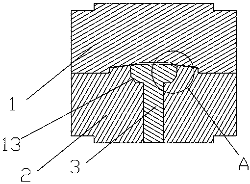
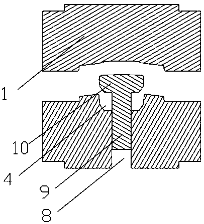
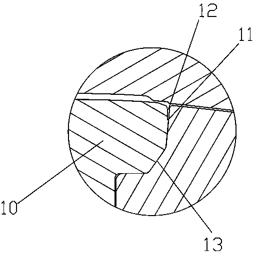
[0028] For specific implementation: see Figure 1 to Figure 3 , a combined mold for an aircraft window frame, comprising an upper mold 1, a lower mold 2 and an inner mold 3, and the upper end of the lower mold 2 is provided with a groove 4 corresponding to the profile of the rib portion of the aircraft window frame 5 The upper groove wall of the groove 4 is provided with a first forming surface corresponding to the outer shape of the rib portion of the aircraft window frame forging, a through hole 8 is provided in the center of the bottom of the groove 4, and the inner mold 3 includes a through hole inserted into the through hole. 8 and the push rod 9 that can be ejected upwards and the forming end 10 that is located above the through hole 8 and matches the shape of the groove 4, the forming end 10 is connected to one end of the push rod 9, and the upper p...


PUM

PropertyMeasurementUnit
thicknessaaaaaaaaaa
heightaaaaaaaaaa

Abstract

The invention discloses a combined mold for a plane window frame. The combined mold comprises an upper mold, a lower mold and an inner mold; a groove is formed in the upper end of the lower mold; a first shaping surface is arranged on the groove wall of the upper part of the groove; a first through hole is formed in the center of the bottom of the groove; the inner mold comprises an ejecting rod which is inserted in the through hole and can be ejected upwards and a shaping tip which is located above the through hole and matched with the groove in shape; a second shaping surface is arranged onthe side wall of the upper part of the shaping tip; after mold closing, the first shaping surface and the second shaping surface are matched to form a rib cavity of a plane window frame forging; and the lower end surface of the upper mold, the upper end surface of the lower mold, the first shaping surface and the second shaping surface are matched to form a forging cavity of the plane window frameforging. The inner mold of the combined mold has both effects of forging shaping and ejection after forging, deformation of a web is avoided during ejection, split-body manufacturing is adopted at the rib cavity of a conventional mold, combined use is performed, and the combined mold has the advantages that demolding is smooth, a forging rib is filled, the forging is not prone to deformation during demolding and manufacturing is easy.

Description

technical field [0001] The invention belongs to the field of aircraft window frame manufacturing, in particular to a combined mold for the aircraft window frame. Background technique [0002] Aircraft window frames, also known as passenger observation windows, are located on both sides of the aircraft fuselage. At the same time, it is also an escape and rescue observation port in case of emergency, which can help the occupants in the cabin choose a suitable escape route, and help rescuers understand the situation in the cabin, which plays an important role in the evacuation of passengers. However, the air pressure outside the aircraft cabin will decrease as the altitude of the aircraft increases, and the temperature will decrease as the altitude increases. As a result, the aircraft window frame will continue to be subjected to loads due to the air pressure difference between the inside and outside of the cabin during its service, which requires the window frame to have reli...

Claims


Application Information

Patent Timeline
Patent Type & Authority Applications(China)
IPC IPC(8): B21J13/02B21J13/03B21J13/14
Inventor 周杰龙帅李世山董旭刚卢顺李慧罗乐
Owner CHONGQING UNIV
Learn More