Flange connecting method

A connection method and flange technology, which is applied to metal processing equipment, manufacturing tools, workpiece edge parts, etc., can solve the problems of flange base plate deformation, many hidden dangers, and extremely high overall flatness requirements, and achieve the effect of avoiding repairs

Inactive Publication Date: 2019-06-21
GUANGZHOU SHIPYARD INTERNATIONAL LTD
View PDF4 Cites 4 Cited by
  • Summary
  • Abstract
  • Description
  • Claims
  • Application Information

AI Technical Summary

Problems solved by technology
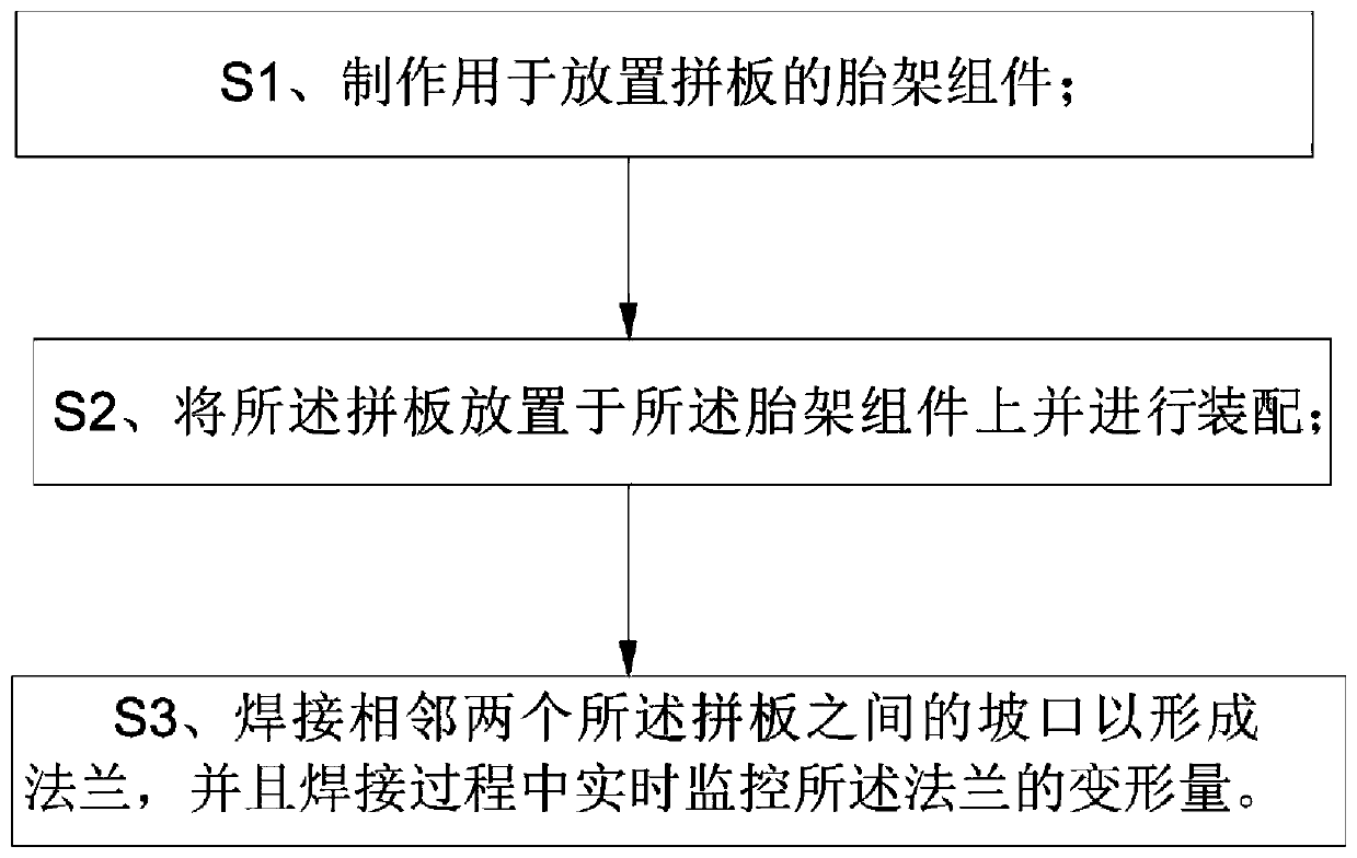
In addition, due to the high requirements on the bearing capacity of the flange, the plate thickness of the flange base is relatively thick, and the overall flatness is extremely high.
Due to the thick plate thickness, large amount of welding, and concentrated thermal stress, the flange base plate is easily deformed, ex

Method used


Image

  • Flange connecting method
  • Flange connecting method
  • Flange connecting method

Examples


Embodiment Construction

[0036] In order to make the purpose, technical solutions and advantages of the embodiments of the present invention clearer, the technical solutions in the embodiments of the present invention will be clearly and completely described below in conjunction with the drawings in the embodiments of the present invention. Obviously, the described embodiments It is a part of embodiments of the present invention, but not all embodiments. The components of the embodiments of the invention generally described and illustrated in the figures herein may be arranged and designed in a variety of different configurations.

[0037] Accordingly, the following detailed description of the embodiments of the invention provided in the accompanying drawings is not intended to limit the scope of the claimed invention, but merely represents selected embodiments of the invention. Based on the embodiments of the present invention, all other embodiments obtained by persons of ordinary skill in the art wi...


PUM


Abstract

The invention discloses a flange connecting method, and belongs to the technical field of shipbuilding. The flange connecting method comprises the steps of S1, manufacturing a bed jig assembly for placing jointed boards; S2, placing the jointed boards onto the bed jig, and assembling; and S4, welding a groove between each two adjacent jointed boards so as to form a flange, and during the welding process, monitoring the deformation of the flange in real time. Through arranging the special bed jig assembly for placing the splicing boards, the problem of instability in flange connection due to unqualified jointed board assembly caused by instable placement is avoided; and meanwhile, through monitoring the deformation of the flange in real time during the welding process, the corresponding measures can be taken when the deformation exceeds a predetermined value, so that the aim of improving the first-pass yield of the flange precision quality is achieved, and unnecessary repair caused by poor control of a middle process is avoided.

Description

technical field [0001] The invention relates to the technical field of shipbuilding, in particular to a flange connection method. Background technique [0002] For ships using azimuth propellers as propulsion methods, the propulsion base usually adopts flange form. Due to the large overall size of the flange, jigsaw work is required. Moreover, due to the high requirements on the bearing capacity of the flange, the thickness of the flange base plate is relatively thick, and the overall flatness requirement is extremely high. Due to the thick plate thickness, large amount of welding, and concentrated thermal stress, the flange base plate is easily deformed, exceeding the allowable deviation range of flatness. [0003] For the jigsaw operation of such large and ultra-thick flanges, there are no clear control procedures and construction methods. There are many hidden dangers in the construction process, and the problem of overall flatness is very easy to appear. [0004] Ther...

Claims


Application Information

Patent Timeline
IPC IPC(8): B23K33/00
Inventor 齐超周圣平吴磊磊
Owner GUANGZHOU SHIPYARD INTERNATIONAL LTD
Why Eureka
Try Eureka