An Adaptive Temperature Control System

A temperature control system and self-adaptive technology, applied in valve details, valve devices, engine components, etc., can solve the problem of unfavorable temperature control of unmanned aerial vehicle heating equipment, unfavorable temperature control of unmanned aerial vehicle heating equipment, unfavorable temperature control of unmanned aerial vehicle heating equipment, etc. UAV heating equipment cooling and other problems, to avoid the heat can not be discharged in time, with self-adaptive, expand the effect of heat dissipation

Active Publication Date: 2021-02-05
HIWING AVIATION GENERAL EQUIP
View PDF8 Cites 0 Cited by
  • Summary
  • Abstract
  • Description
  • Claims
  • Application Information

AI Technical Summary

Problems solved by technology

In this process, the precise measurement of the temperature sensor and the reliable operation of the temperature control processor and the flow control valve are required as preconditions. If any link fails, the entire system will fail, which is not good for the temperature control of the drone’s onboard heating equipment.
In addition, the use of ram air heat exchange and single-phase liquid cooling circuit heat exchange has limited heat exchange capacity, which is only effective for temperature control of heating equipment with low power heat flux density, and for instantaneous high power pulse or continuous high heat flux heat generation As far as the equipment is concerned, it is impossible to quickly cool down the heating equipment of the drone, and it is easy to cause the temperature of the equipment to overheat.
[0005] In summary, the conventional passive thermal control and active thermal control schemes have many disadvantages for the temperature control of UAV heating equipment with complex performance, high system integration and frequent changes in working modes.

Method used


Image

  • An Adaptive Temperature Control System
  • An Adaptive Temperature Control System
  • An Adaptive Temperature Control System

Examples


Embodiment Construction

[0036]It should be noted that, in the case of no conflict, the embodiments in the present application and the features in the embodiments can be combined with each other. The following will clearly and completely describe the technical solutions in the embodiments of the present invention with reference to the accompanying drawings in the embodiments of the present invention. Obviously, the described embodiments are only some, not all, embodiments of the present invention. The following description of at least one exemplary embodiment is merely illustrative in nature and in no way taken as limiting the invention, its application or uses. Based on the embodiments of the present invention, all other embodiments obtained by persons of ordinary skill in the art without creative efforts fall within the protection scope of the present invention.

[0037] It should be noted that the terminology used here is only for describing specific implementations, and is not intended to limit th...


PUM


Abstract

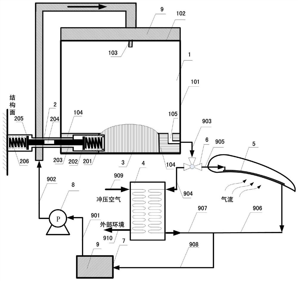
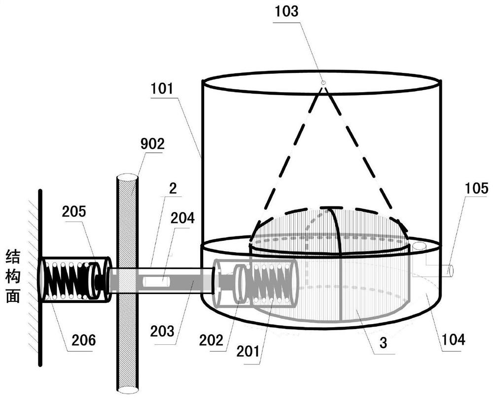
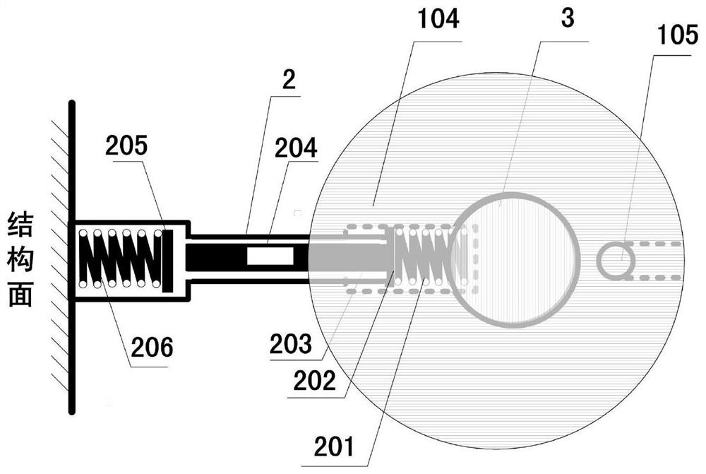
The present invention provides an adaptive temperature control system. The adaptive temperature control system includes: a spray module, which has a liquid outlet component, and is used to spray fluid working fluid on the surface of a heating device; a phase change material, which is arranged along the circumferential direction of the heating device , which controls the temperature of the heating device before it is completely melted; the self-adaptive valve body is arranged on the liquid outlet component, and is used to open or close the liquid outlet component to realize the temperature control of the heating device after the phase change material is completely melted. temperature control. When the power of the heating equipment is low, the phase change material is used to control the temperature; when the power is high, the phase change material is completely melted, and the temperature continues to rise, and the temperature is controlled through the combination of the adaptive valve body and the spray module; the adaptive temperature control of the heating equipment is realized. The heat transfer process is self-adaptive, without the need for temperature measurement and calculation by a temperature-controlled processor.

Description

technical field [0001] The present invention proposes an adaptive temperature control system, which is suitable for adaptive temperature control of heating equipment of unmanned aerial vehicles. Background technique [0002] The performance and functions of UAVs have increased, and the heating power of airborne heating equipment varies greatly in different flight stages due to different working modes, and more stringent requirements are put forward for the adaptive temperature control requirements of heating equipment. [0003] At present, there are two ways to control the temperature of heating equipment on board drones: passive control and active temperature control. Passive temperature control of phase change materials and passive temperature control relying on structural equipment are relatively common temperature control methods. The method of passive temperature control relying on structural design has no self-adaptive ability, and for equipment with large changes in h...

Claims


Application Information

Patent Timeline
Patent Type & Authority Patents(China)
IPC IPC(8): B64D47/00F16K31/70
Inventor 张红生田晓威刘忠诚邢艳丽曹薇薇
Owner HIWING AVIATION GENERAL EQUIP
Why Eureka
Try Eureka