
Carton conveying frame with transferring device

A technology for transfer devices and conveyor racks, which is applied in the direction of conveyors, conveyor objects, conveyor control devices, etc., and can solve problems such as insufficient automation, large manual labor, and no central transfer mechanism.

Inactive Publication Date: 2019-06-21
江思琼
View PDF9 Cites 2 Cited by
  • Summary
  • Abstract
  • Description
  • Claims
  • Application Information

AI Technical Summary

Problems solved by technology

[0002] The existing corrugated boxes need to be transported after the packaging is completed. The existing transport racks generally only have linear transport, and after being transported to a station for processing, they need to be transported to a trolley and transported to another station by manual push. On a conveyor frame, there is no middle transfer mechanism, which makes the transition in the middle troublesome, with a large amount of manual labor, and the degree of automation is not high enough

Method used


Image

  • Carton conveying frame with transferring device
  • Carton conveying frame with transferring device
  • Carton conveying frame with transferring device

Examples


Embodiment

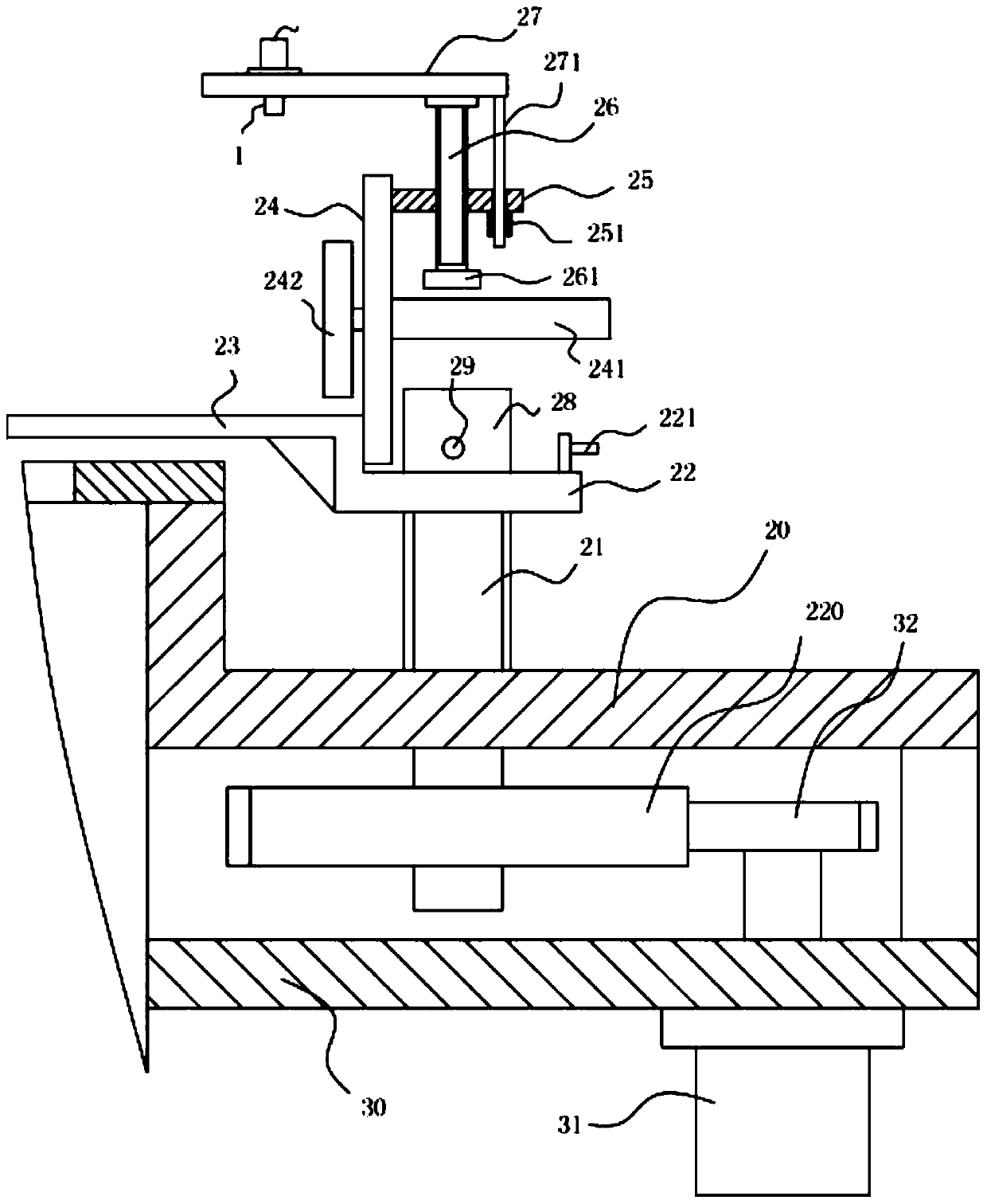
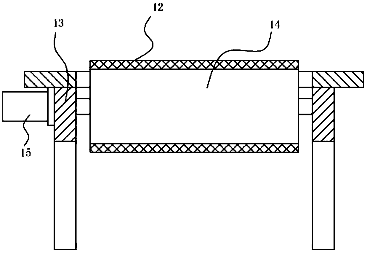
[0020] Example: see Figure 1 to Figure 3 As shown, a carton conveying rack with a transfer device includes a conveying rack 10. The middle of the top plate of the conveying rack 10 has a main conveying trough 11, the conveying belt 12 is in the conveying main trough 11, and the top plate of the conveying rack 10 An upper support frame 20 is fixed on the right bottom surface of the upper support frame 20. The middle of the top plate of the upper support frame 20 is hinged with a rotating main shaft 21 through a bearing. The top end of the rotating main shaft 21 extends from the top plate of the upper support frame 20 and is fixed with a rotating plate 22. The rotating plate 22 A bent splice plate 23 is formed at the left end of the bent splice plate 23, and the left part of the horizontal part of the bent splice plate 23 is above the right part of the top plate of the conveyor rack 10 and corresponds to the right end of the conveyor belt 12;

[0021] The bottom surface of the upp...


PUM


Abstract

The invention discloses a carton conveying frame with a transferring device. The carton conveying frame comprises a conveying frame body, a conveying main through groove is formed in the middle of a top plate of the conveying frame body, a conveying belt is located in the conveying main through groove, an upper supporting frame is fixed to the bottom face of the right part of the top plate of theconveying frame body, a rotating main shaft is hinged to the middle of a top plate of the upper supporting frame through a bearing, the top end of the rotating main shaft stretches out of the top plate of the upper supporting frame, a rotating plate is fixed to the top end of the rotating main shaft, a bending material-receiving plate is formed at the left end of the rotating plate, and the left part of a horizontal part of the bending material-receiving plate is located above the right part of the top plate of the conveying frame body and corresponds to the right end of the conveying belt; and a lower supporting frame is fixed to the bottom face of the upper supporting frame, the bottom end of the rotating main shaft stretches out of the bottom face of the top plate of the upper supporting frame, a transmission gear is fixed to the bottom end of the rotating main shaft, and a main rotating motor is fixed to the bottom face of a bottom plate of the lower supporting frame. The carton conveying frame can transfer cartons on the conveying frame body and push the cartons to another conveying frame, perpendicular to the conveying frame body, of a subsequent station, seamless butting isachieved, and the conveying needs of connecting processing of the cartons are met.

Description

Technical field [0001] The invention relates to the technical field of corrugated cardboard manufacturing equipment, and more specifically to a carton conveying rack with a transfer device. Background technique [0002] The existing corrugated boxes need to be transported after the packaging is completed. The existing transport racks generally only have linear transport, and after transporting to one station for processing, they need to be transported to the cart, and transported to another by manual pushing. On a conveying rack, there is no middle transfer mechanism, which makes the middle transition troublesome, a lot of manual labor, and the degree of automation is not high enough. Summary of the invention [0003] The purpose of the present invention is to address the shortcomings of the prior art and provide a carton conveying rack with a transfer device, which can transfer the carton on the conveying rack and push it to the conveying rack of the subsequent station perpendicu...

Claims


Application Information

Patent Timeline
Patent Type & Authority Applications(China)
IPC IPC(8): B65G23/22B65G23/04B65G43/08B65G47/82
Inventor 江思琼
Owner 江思琼
Learn More