
Chain lubrication device for curing furnace

A technology for lubricating devices and curing furnaces, applied in cleaning devices, transportation and packaging, conveyor objects, etc., can solve problems such as poor effect and high fuel consumption, and achieve the effect of improving operation stability and efficient and precise spraying

Pending Publication Date: 2019-06-21
桐乡双玛机械有限公司
View PDF10 Cites 0 Cited by
  • Summary
  • Abstract
  • Description
  • Claims
  • Application Information

AI Technical Summary

Problems solved by technology

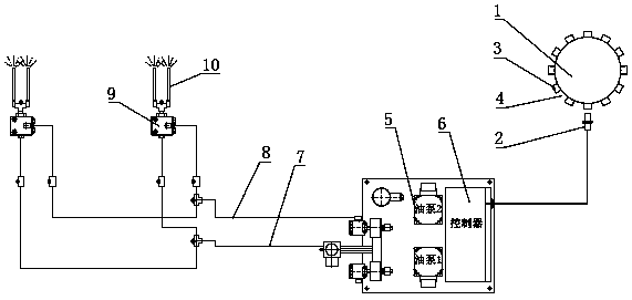
[0005] During the operation of the above scheme, the time when the protrusions or grooves on the disc pass through the sensing element is used to determine the time when the chain joint passes the oil outlet nozzle and the positioning node, so that the joint position of the chain can be accurately adjusted after calibration. Oil injection lubrication, during the oil injection process, the gas output by the air pump and the lubricating oil delivered by the oil pump are mixed at the connection between the air cavity and the oil cavity to form a mixture of oil and gas, which is sprayed out to lubricate the joints of the chain, effectively solving the problem. In the prior art, the lubricating oil is applied to the chain, resulting in defects such as poor effect and high oil consumption, so as to realize efficient and accurate spraying of the chain joints

Method used


Image

  • Chain lubrication device for curing furnace
  • Chain lubrication device for curing furnace
  • Chain lubrication device for curing furnace

Examples


Embodiment 1

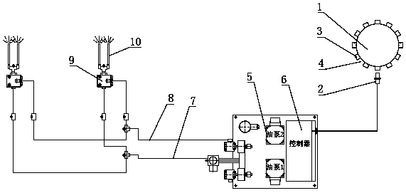
[0017] Such as figure 1 As shown, a chain lubricating device for a curing furnace described in this embodiment includes a disc 1, an induction element 2, an oil pump 5, an air pipe body 7 connected to the air pump, an oil-gas mixing distribution block 9, an oil outlet spray Pipe 10, controller 6; said oil-gas mixing distribution block 9 has an air passage chamber and an oil passage chamber, and correspondingly has an air passage inlet and an oil passage inlet. The air passage chamber and the oil passage chamber are connected, and the connection is provided with The mixture outlet is connected to the oil outlet nozzle 10; the oil pump 5 is connected to the oil passage inlet on the oil-gas mixing distribution block 9 through the oil pipe 8; the other end of the air pipe body 7 connected to the air pump is connected to the The gas path inlet on the oil-gas mixing distribution block 9 is connected; the oil-gas mixing distribution block 9 is at least one pair, and each pair is two,...

Embodiment 2

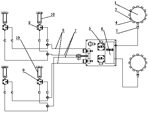
[0020] Such as figure 2 As shown, a chain lubricating device for a curing furnace described in this embodiment includes a disc 1, an induction element 2, an oil pump 5, an air pipe body 7 connected to the air pump, an oil-gas mixing distribution block 9, an oil outlet spray Pipe 10, controller 6; said oil-gas mixing distribution block 9 has an air passage chamber and an oil passage chamber, and correspondingly has an air passage inlet and an oil passage inlet. The air passage chamber and the oil passage chamber are connected, and the connection is provided with The mixture outlet is connected to the oil outlet nozzle 10; the oil pump 5 is connected to the oil passage inlet on the oil-gas mixing distribution block 9 through the oil pipe 8; the other end of the air pipe body 7 connected to the air pump is connected to the The gas path inlet on the oil-gas mixing distribution block 9 is connected; the oil-gas mixing distribution block 9 is at least one pair, and each pair is two...


PUM


Abstract

The invention relates to a lubrication mechanism, in particular to a mechanism for lubricating chains in a curing furnace. The mechanism comprises a disc, an induction element, an oil pump, a gas pathpipe body connected with a gas pump, oil-gas mixing distribution blocks, oil outlet spraying pipes and a controller. At least one pair of oil-gas mixing distribution blocks are arranged, each pair comprises two oil-gas mixing distribution blocks, in other words, the corresponding oil outlet spraying pipe of one oil-gas mixing distribution block corresponds to a joint at one position of the chainon one side, and each joint of the chain on the other side corresponds to the corresponding oil outlet spraying pipe of the other oil-gas mixing distribution block. Protrusions are arranged on the circumference edge of the disc at equal intervals, grooves are formed between the protrusions, and the induction element is connected with the controller through a wire. An obtained chain lubrication device for the curing furnace has the characteristics of being good in oil spraying effect, accurate in point fixing, little in waste, high in efficiency, convenient to use and the like.

Description

technical field [0001] The invention relates to a lubricating mechanism, especially a mechanism for lubricating chains in a curing furnace. Background technique [0002] In the curing furnace, the two sides of the conveyor belt transmit the material through the chain mechanism, and then send the material to the curing furnace for curing treatment. Since the curing furnace is at a high temperature, the life of the lubricating oil on the chain is very short during the transmission process. There is no lubricating oil on the chain after going in and out of the curing furnace several times, and the joints of the chain need to be re-applied or sprayed with lubricating oil. Now the usual method is to use a brush to paint, but this method is inefficient and the effect is not good . Contents of the invention [0003] The object of the present invention is to overcome the deficiencies of the prior art and provide a chain lubricating device for a curing furnace that can quickly and...

Claims


Application Information

Patent Timeline
Patent Type & Authority Applications(China)
IPC IPC(8): B65G45/08
Inventor 濮志衡濮良晨
Owner 桐乡双玛机械有限公司
Learn More