Geological drilling equipment

A technology for geological drilling and equipment, applied in drilling equipment, drilling equipment and methods, earthwork drilling, etc., can solve the problems of inability to reduce, no cooling and cooling device, etc., and achieve the effect of increasing stability

Active Publication Date: 2019-06-21
梁军
View PDF10 Cites 2 Cited by
  • Summary
  • Abstract
  • Description
  • Claims
  • Application Information

AI Technical Summary

Problems solved by technology

[0002] For example, the patent number is CN201710246531.2, a kind of drilling equipment. This excavating equipment needs to be constructed in cooperation with web piles. Adjacent web piles are separated by a distance of one bite pile, and excavation equipment is used to manufacture a bite pile between every two adjacent web piles, so that the two left and right ends of each bite pile are depressed. The two protrusions of the web piles at the left and right ends are respectively aligned to form the bite of the web pile and the bite pile. However, the disadvantage of this invention is that there is no cooling device during the excavation process, and the equipment cannot be reduced During the process, the temperature of the excavation device

Method used


Image

  • Geological drilling equipment
  • Geological drilling equipment
  • Geological drilling equipment

Examples


specific Embodiment approach 1

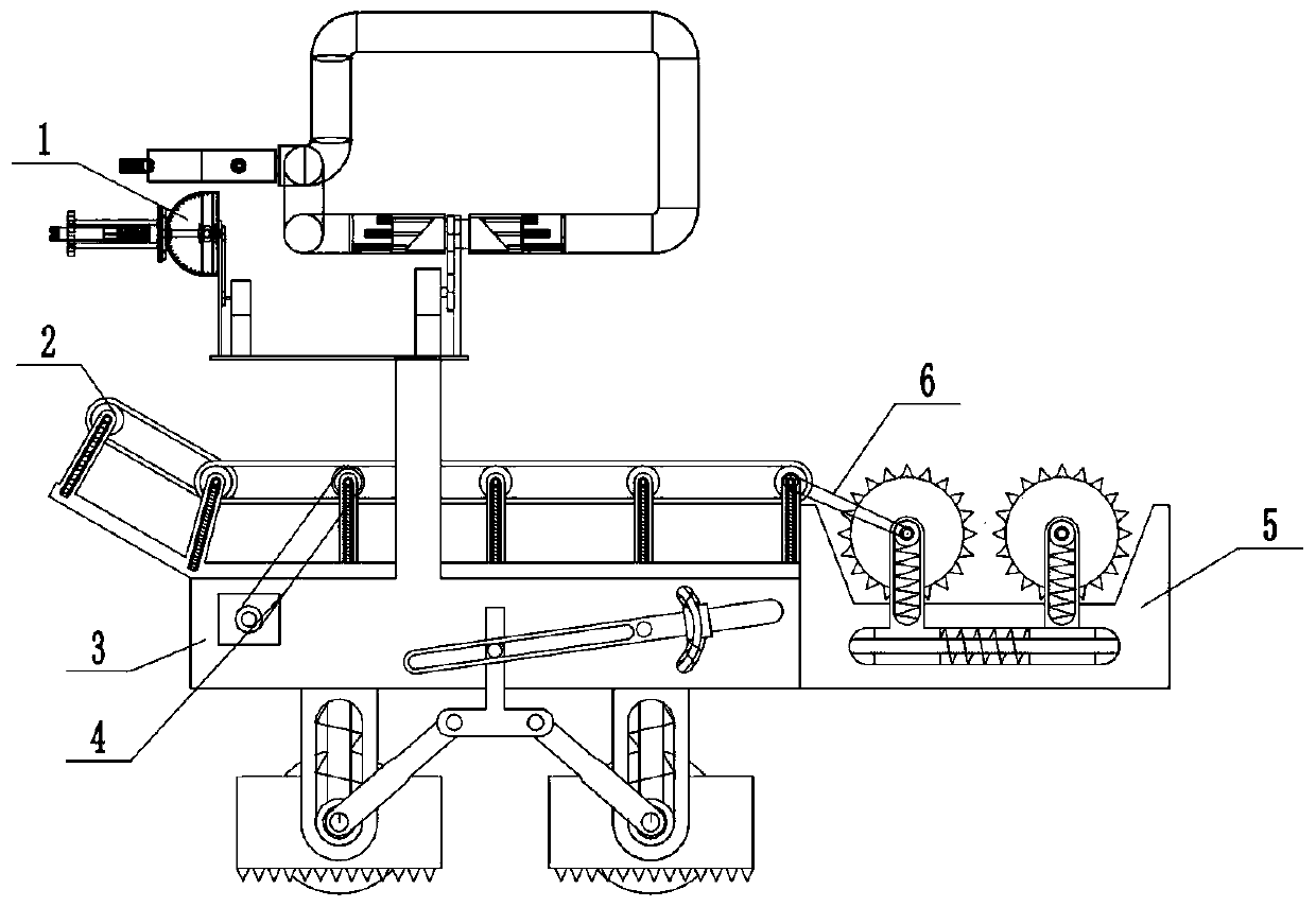
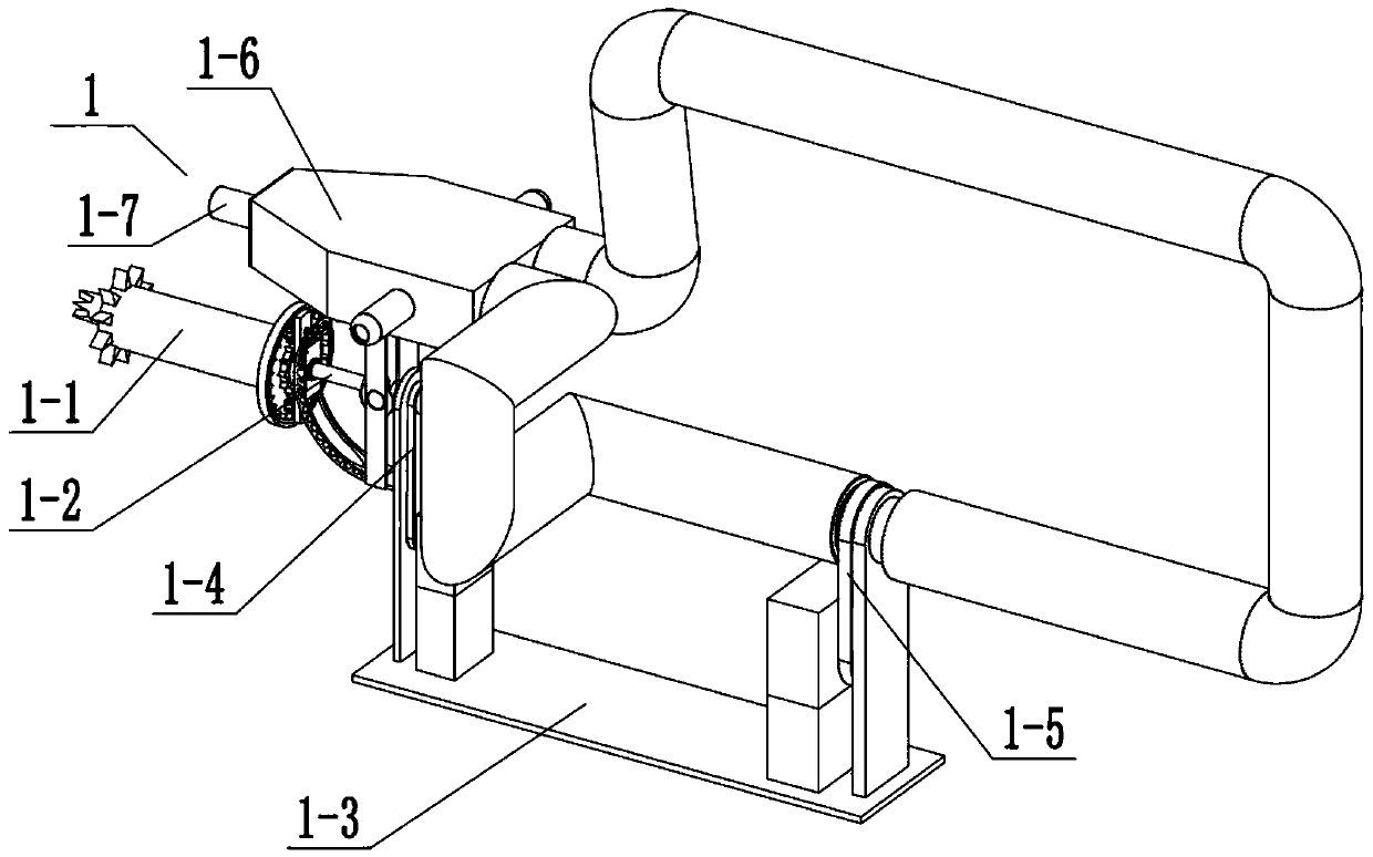
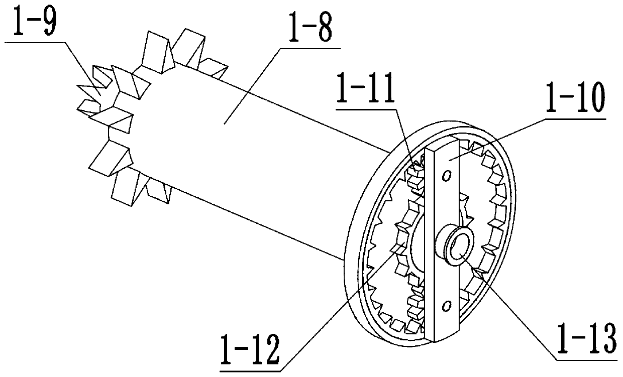
[0045] Combine below Figure 1-24 Describe this embodiment, a kind of geological drilling equipment, including drilling device 1, transport device 2, connecting belt 4, fixed adjustment bracket 3 and crushing device 5, said drilling device 1 includes drilling rod 1-1, angle adjustment rod 1- 2. Fixed frame 1-3, connecting belt 1-4, connecting belt 2 1-5, water spray device 1-6, one-way water spray port 1-7, outer cutting rod 1-8, inner cutting rod 1- 9. Planetary turret 1-10, planetary gear 1-11, sun gear 1-12, transmission pulley 1-13, inner end push spring 1-14, inner end rotating rod 1-15, arc fixed rod 1-16 , Arc card table 1-17, drive rod 1-18, angle slide table 1-19, angle push plate 1-20, push plate push spring 1-21, drive bevel gear 1-22, transmission bevel gear 1-23 , Transmission bevel gear fixed plate 1-24, input rod 1-25, input bevel gear 1-26, middle arc waist groove 1-27, drive sleeve 1-28, piston push rod 1-29, push rod pull Spring 1-30, water spray frame 1-31...

specific Embodiment approach 2

[0053] Combine below Figure 1-24 This embodiment will be described. This embodiment will further describe Embodiment 1. The push plate push spring 1-21 is in a compressed state, and the inner end push spring 1-14 is in a compressed state.

specific Embodiment approach 3

[0055] Combine below Figure 1-24 This embodiment will be described. The first embodiment will be further described in this embodiment. There are two planetary gears 1-11, and the two planetary gears 1-11 are both meshed with the sun gear 1-12 for transmission.


PUM


Abstract

The invention relates to engineering machinery, in particular to geological drilling equipment. According to the geological drilling equipment, an outer cutting rod and an inner cutting rod can be cooled through a water spraying device in a drilling device, and the phenomenon that in the drilling process, the equipment is damaged due to the fact that the equipment is overheated can be avoided; thedrilling angle of the drilling device can be adjusted; ores falling in the drilling process can be conveyed through a conveying device, so that the drilling process can be carried out conveniently and smoothly; and the ores falling in the drilling process can be crushed through a crushing device. The geological drilling equipment comprises the drilling device, the conveying device, a connecting belt, a fixed adjusting bracket and the crushing device; by means of the engaged transmission of a planetary rotating stand, a planetary gear and a sun gear, the stability of the outer cutting rod andthe inner cutting rod in the drilling device can be improved; and an angle push plate is pushed manually from the rear side so as to enable the angle push plate to be separated from an arc-shaped clamping table.

Description

technical field [0001] The invention relates to a construction machine, more specifically a geological drilling equipment. Background technique [0002] For example, the patent number is CN201710246531.2, a kind of drilling equipment. This excavating equipment needs to be constructed in cooperation with web piles. Adjacent web piles are separated by a distance of one bite pile, and excavation equipment is used to manufacture a bite pile between every two adjacent web piles, so that the two left and right ends of each bite pile are depressed. The two protrusions of the web piles at the left and right ends are respectively aligned to form the bite of the web pile and the bite pile. However, the disadvantage of this invention is that there is no cooling device during the excavation process, and the equipment cannot be reduced During the process, the temperature of the excavation device. Contents of the invention [0003] The purpose of the present invention is to provide a ...

Claims


Application Information

Patent Timeline
Patent Type & Authority Applications(China)
IPC IPC(8): E21B7/02E21B15/00E21C25/68E21C35/20
Inventor 刘梦雨
Owner 梁军
Why Eureka
Try Eureka