
Support combination

A pair of support sleeve technology, applied in the connection of rods, connecting components, mechanical equipment, etc., can solve the problems of long installation time, unstabilized vertical head nuts, and many brackets falling

Pending Publication Date: 2019-06-21
苏州华固建筑配套工程有限公司
View PDF1 Cites 3 Cited by
  • Summary
  • Abstract
  • Description
  • Claims
  • Application Information

AI Technical Summary

Problems solved by technology

If the abutment is not tight or there is a slight deviation in position, then the drop nut cannot be tightened stably against the connection part
When the bracket is combined to carry the pipeline, especially after the heavy-duty water pipe and other pipelines, or after a long installation time, or after encountering vibration (for example, the combination of brackets installed in high-speed rail stations and subway stations), it is easy for the installation rail to slide out and the bracket more or less
The vertical head nut and the edge section of the side wall are close to the inside of the installation rail, so it is difficult to adjust, inspect and maintain after the installation is completed, thus leaving a potential safety hazard
[0007] Therefore, the present invention attempts to provide an alternative, changing the connection mode between the guide rails, so that the installation workers can easily and conveniently check whether the connection between the guide rails is stable, and can timely repair after installation, thereby avoiding the existing There are technical problems of potential safety hazards in the use of steel snap locks and vertical head nuts in the foundation

Method used


Image

  • Support combination
  • Support combination
  • Support combination

Examples


Embodiment 1

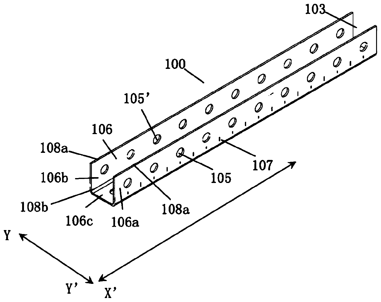
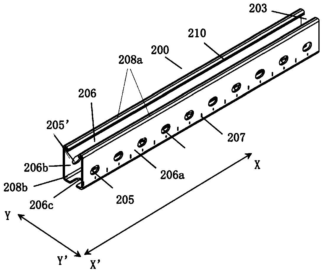
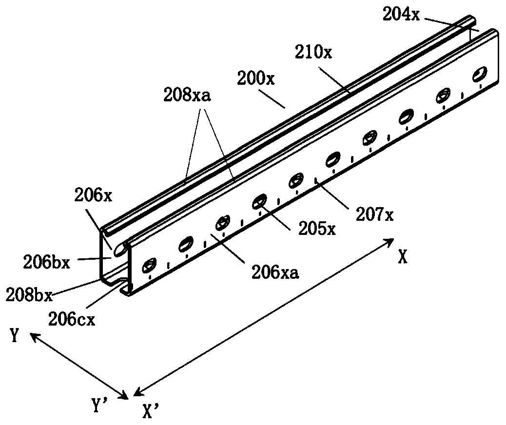
[0103] Embodiment 1 discloses a bracket combination, including a first guide rail (also referred to as a "vertical beam" in some embodiments) 100 and a second guide rail (also referred to as a "support beam" in some embodiments) ) 200, the first guide rail 100 adopts a U-shaped groove structure, including a first guide rail wall 106 and a first notch 103, and at least a pair of first installation holes 105 are provided on the first guide rail wall 106. The second guide rail 200 adopts a U-shaped groove structure, including a second guide rail wall 206 and a second notch 203, and the second guide rail wall 206 is provided with at least one pair of second mounting holes (in some embodiments, it may also be referred to as "support beam screw holes") 205 . In this embodiment, the width of the first notch 103 (ie figure 1 , the opening size of the first notch 103 along the Y-Y' direction) is greater than the width of the second rail (ie figure 1 , the size of the second guide rai...

Embodiment 2

[0132] See Figure 4. The difference between this embodiment and Embodiment 1 is that the bracket assembly further includes a base 400 . The base 400 includes at least one base fixing part 402 and at least one base rail connecting part 404 . The base 400 may be fixed on a surface (eg, wall, ground, steel structure) by the at least one base fixing member 402 . The base 400 can be fixedly connected to the first guide rail 100 through the at least one base guide rail connector 404 .

[0133] In some embodiments, the base rail connector 404 includes a plurality of base side walls 406, the base side walls 406 are provided with base mounting holes 405, and the plurality of base side walls 406 are connected to the first rail wall. 106 is fixedly connected by penetrating bolts 101 passing through the base installation hole 405 and the first installation hole 105 .

[0134] In some embodiments, the base fixture 402 employs one or more flat plates 402 a , 402 b vertically connected to...

Embodiment 3

[0141]The difference between this example and Example 1 is that the bracket combination further includes a fall prevention connector (also referred to as a "right-angle connector" in some embodiments) 500, including a first guide rail connection area 500a and a second guide rail Connection area 500b. The first guide rail connection area 500 a can be placed in the first notch 103 and fixedly connected with the first guide rail 100 . The second guide rail connection area 500 b can be placed in the second notch 203 and fixedly connected with the second guide rail 200 .

[0142] In some embodiments, the anti-fall connector 500 includes two parallel first anti-fall fixing plate 501 , second anti-fall fixing plate 502 and anti-fall connecting plate 503 . The anti-fall connecting plate 503 is vertically arranged between the first anti-fall fixing plate 501 and the second anti-fall fixing plate 502, and connects the first anti-fall fixing plate 501 and the second anti-fall fixing pla...


PUM


Abstract

The invention provides a support combination which comprises a first guide rail and a second guide rail. The first guide rail is of a U-shaped groove structure and comprises a first guide rail wall and a first slot, the first guide rail wall is provided with at least one pair of first installation holes, the second guide rail is a U-shaped groove mechanism and comprises a second guide rail wall and a second slot, and the second guide rail wall is provided with at least one pair of second installation holes. The support combination is characterized in that the width of the first slot is largerthan the width of the second guide rail, one end of the second guide rail is placed in the first slot, and the first guide rail and the second guide rail oppositely penetrate through the first installation holes and the second installation holes through opposite penetrating bolts to be fixedly connected. An installation method is easy, a constructor can conveniently inspect bolt installation and fastening conditions, quality testing and maintenance are facilitated for the support combination, and potential safety hazards are eliminated in time.

Description

[0001] related application [0002] This application requires the priority of (i) Chinese Utility Model Application 201821049507.6 "An Indoor Anti-fall Bracket for Buildings" and (ii) 201821046477.3 "A Right-angle Connector Structure for Indoor Anti-Fall Brackets for Buildings" submitted on July 3, 2018 rights, these utility model applications are incorporated by reference in their entirety. technical field [0003] The invention belongs to the technical field of building auxiliary facilities, and in particular relates to a bracket combination. Background technique [0004] The finished bracket is a bracket system that is directly produced by the factory to produce shaped channel steel and various connectors, and then handed over to the construction personnel for on-site assembly. This support system can be used to support various pipes and pipelines, which is of great significance in the indoor installation of buildings. When the finished bracket is assembled into a door-...

Claims


Application Information

Patent Timeline
IPC IPC(8): F16B7/18
Inventor 李明
Owner 苏州华固建筑配套工程有限公司
Learn More