
Mini-tiller shifting speed changing mechanism and mini-tiller comprising same

A speed change mechanism and micro-tiller technology, applied in the field of micro-tillers, can solve the problems of inability to operate normally for a long time, reduced power transmission reliability, and inability to meet agricultural production, etc., and achieve strong impact resistance, flexible speed control, and power. Low loss effect

Inactive Publication Date: 2019-06-21
重庆轩通机电有限公司
View PDF0 Cites 0 Cited by
  • Summary
  • Abstract
  • Description
  • Claims
  • Application Information

AI Technical Summary

Problems solved by technology

However, in the prior art, the gear shifting mechanism of the micro tillage machine generally has complex structures, long power transmission routes that reduce the reliability of power transmission, inconvenient gear shifting operations, poor flexibility, and low stability. 1. Under the condition of poor lubricating conditions, it cannot run normally for a long time and cannot meet the needs of agricultural production.

Method used


Image

  • Mini-tiller shifting speed changing mechanism and mini-tiller comprising same
  • Mini-tiller shifting speed changing mechanism and mini-tiller comprising same
  • Mini-tiller shifting speed changing mechanism and mini-tiller comprising same

Examples


Embodiment Construction

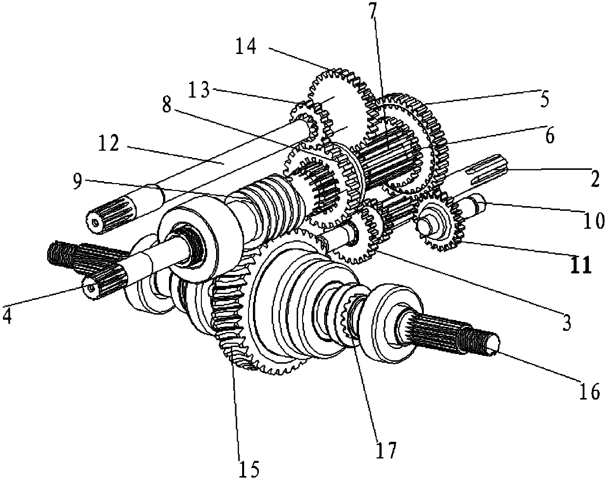
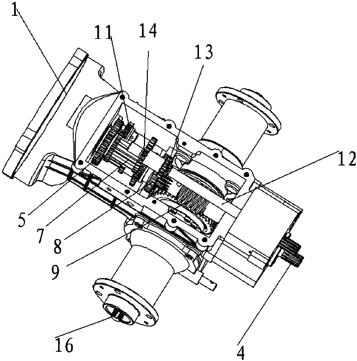
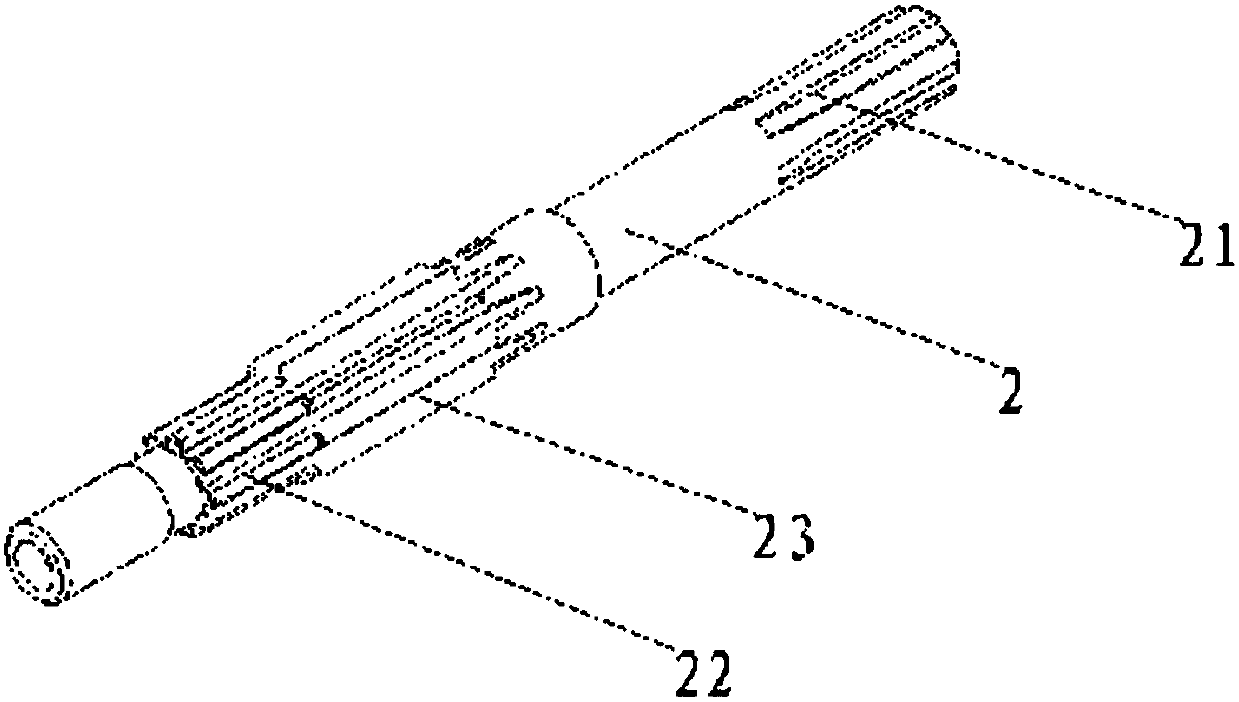
[0022] figure 1 It is a schematic diagram of the structure of the present invention, figure 2 It is a schematic diagram of structural assembly of the present invention, image 3 It is a schematic diagram of the main shaft structure, as shown in the figure: the gear shifting mechanism of the tiller in this embodiment includes a casing 1, a main shaft assembly, a gear shifting assembly and a reverse gear assembly. Of course, the casing in this embodiment is also provided with There is a shift fork, and it is provided with a driving device for driving the shift fork, which is used to adjust the positions of the worm meshing teeth, countershaft shift teeth and shift double teeth, which belongs to the prior art and will not be repeated here. repeat;

[0023] The main shaft assembly includes a main shaft double tooth 3 for fixing the power input main shaft 2 and the outer casing to the main shaft 2;

[0024] The shifting transmission assembly includes a layshaft 4 and synchronou...


PUM


Abstract

The invention discloses a mini-tiller shifting speed changing mechanism. The mechanism comprises a box body, a spindle assembly, a shifting speed changing assembly and a reverse shifting assembly. Theshifting speed changing assembly comprises a countershaft, a synchronous dual gear, a countershaft shifting gear, a shifting dual gear, a countershaft ring gear and a worm, wherein the synchronous dual gear, the countershaft shifting gear, the shifting dual gear, the countershaft ring gear and the worm are sequentially arranged on the countershaft in a sleeving mode; the shifting speed changing assembly further comprises a worm meshing gear for controlling the countershaft ring gear and the worm to be engaged and disengaged; and the worm meshing gear is arranged on the worm in a sleeving modeand can move in the axial direction of the worm. Through mutual cooperation of three shifting devices of the countershaft shifting gear, the shifting dual gear and the worm meshing gear, walking shifting of a mini-tiller is achieved, more gears are set, the speed of the mini-tiller is controlled more flexibly, and the selectivity is higher under different environments. The invention further discloses a mini-tiller using the mini-tiller shifting speed changing mechanism. has small power loss and low failure rate. The mini-tiller has the characteristics of lower power loss and fault rate and high reliability, is low in noise and can work normally in various complicated work places and environments.

Description

technical field [0001] The invention relates to the field of micro tillage machines, in particular to a gear shift mechanism of the micro tillage machine and the micro tillage machine. Background technique [0002] As a small agricultural mechanical device, the tiller is playing an increasingly important role in plowing, plowing, pruning and weeding. However, in the prior art, the gear shifting mechanism of the micro tillage machine generally has complex structures, long power transmission routes that reduce the reliability of power transmission, inconvenient gear shifting operations, poor flexibility, and low stability. 1. Under the condition of poor lubricating conditions, it cannot run normally for a long time and cannot meet the needs of agricultural production. [0003] Therefore, it is necessary to improve the gear shifting mechanism of the tiller, so that it has simple structure, reliable power transmission, flexible and convenient gear shifting, more flexible speed ...

Claims


Application Information

Patent Timeline
IPC IPC(8): F16H3/083F16H3/091F16H57/023A01B71/00
Inventor 周伟
Owner 重庆轩通机电有限公司
Learn More