Novel pulverizer capable of being automatically controlled

An automatic control, pulverizer technology, applied in non-rotational vibration suppression, dust removal, grain processing, etc., can solve problems such as injury to personnel, pulverizer vibration, inability to disassemble and replace, etc., to save power costs, convenient and fast operation, and prevent random drift effect

Inactive Publication Date: 2019-06-25
杜瑜
View PDF0 Cites 0 Cited by
  • Summary
  • Abstract
  • Description
  • Claims
  • Application Information

AI Technical Summary

Problems solved by technology

For the large pulverizers in the existing market, the conveyed materials are easy to be blocked on the screening roller, which makes the material conveyance unsmooth and affects the production progress. In severe cases, it will cause machine failure and cause great economic losses; the cavity in the pulverizer The rotor inside is rotating at a high speed, hitting the material, which may cause the material to be shot out of the outside through the channel at the feed inlet under strong impact, which will hurt personnel; most of the crushing mechanisms on the rotor are welded and cannot be disassembled and replaced. The adaptability of the pulverizer is not strong; the pulverizer will produce a lot of noise when it is working, forming noise pollution, affecting the normal information exchange and transmission in the production process, and it is not conducive to people's health; Vibration, working for a long time will cause damage to the equipment

Method used


Image

  • Novel pulverizer capable of being automatically controlled

Examples


Embodiment Construction

[0016] The following will clearly and completely describe the technical solutions in the embodiments of the present invention with reference to the accompanying drawings in the embodiments of the present invention. Obviously, the described embodiments are only some, not all, embodiments of the present invention. All other embodiments obtained by persons of ordinary skill in the art based on the embodiments of the present invention belong to the protection scope of the present invention.

[0017] According to an embodiment of the present invention, a new pulverizer that can be automatically controlled is provided.

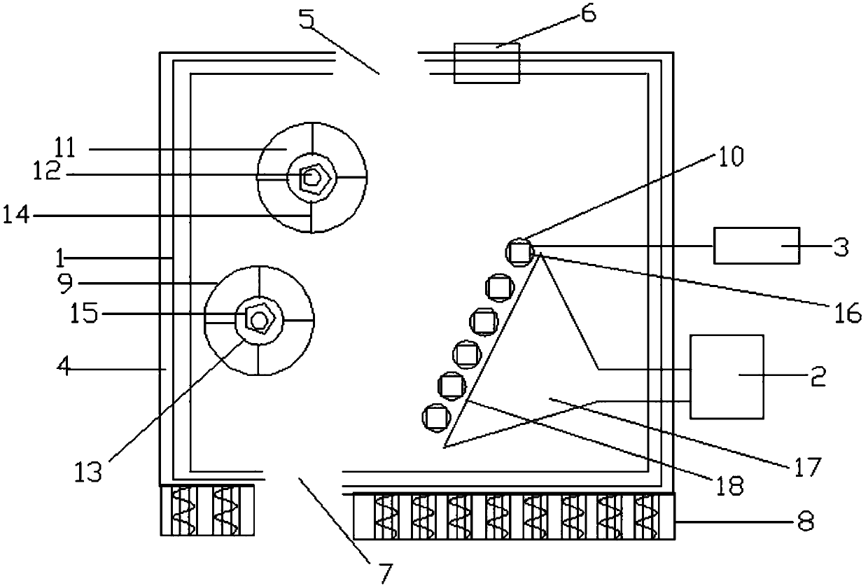
[0018] Such as figure 1 As shown, a new type of pulverizer that can be automatically controlled according to the embodiment of the present invention includes a casing 1, an air compressor 2 and a control computer 3, and the air compressor 2 and the control computer 3 are arranged on the machine. The outer side of the casing 1, the control computer 3 is connected wi...


PUM


Abstract

The invention discloses a novel pulverizer capable of being automatically controlled. The novel pulverizer comprises a machine enclosure, an air compressor and a control computer, wherein a soundproofstructure is arranged on the outer part of the machine enclosure; a charge hole is formed in the upper end of the machine enclosure; a dust sucking device is arranged at one side of the charge hole;a discharge hole is formed in the lower end of the machine enclosure; the bottom of the housing is equipped with a damping mechanism; a rotor and a screening roller are arranged inside the machine enclosure; the rotor comprises a rotary disc and a straight rod; a tool rest is arranged on the straight rod in a sleeving mode; a plurality of groups of blades are arranged on the tool rest; a fixed nutis arranged at the outer side of the blade on the straight rod; a twisting force detector is arranged on the rotary shaft of the screening roller; the twisting force detector is connected to the control computer; an air blowing barrel is arranged on the air compressor; and a screen is arranged between the screening roller and the air blowing barrel. The novel pulverizer capable of being automatically controlled disclosed by the invention is simple in structure, is convenient and quick in operation, and has the advantages of being automatic in control, soundproof, damping, sucking dust, beingstrong in adaptation, and the like.

Description

technical field [0001] The invention relates to the technical field of mechanical manufacturing, in particular to a new type of pulverizer that can be automatically controlled. Background technique [0002] As a commonly used crushing device, the pulverizer is widely used in all walks of life. For the large pulverizers in the existing market, the conveyed materials are easy to be blocked on the screening roller, which makes the material conveyance unsmooth and affects the production progress. In serious cases, it will cause machine failure and cause great economic losses; the cavity in the pulverizer The rotor inside is rotating at a high speed, hitting the material, which may cause the material to be shot out of the outside through the channel at the feed inlet under strong impact, which will hurt personnel; most of the crushing mechanisms on the rotor are welded and cannot be disassembled and replaced. The adaptability of the grinder is not strong; the grinder will produc...

Claims


Application Information

Patent Timeline
IPC IPC(8): B02C18/14B02C18/18B02C18/16B02C23/08B02C23/24B02C25/00B08B15/04F16F15/04
Inventor 杜瑜
Owner 杜瑜
Why Eureka
Try Eureka